QO-100 Experiments – ADF4351 SynthShield

I’ve recently used a number of ADF4351 modules in various projects. The last two modules have been used to provide a single fixed frequency output. An Arduino Nano running the F1CJN single frequency sketch is used to control the ADF4351.

The unit above is the 2256MHz LO (Local Oscillator) currently used in my QO-100 transmit up-converter.

This second one provides 40MHz for the Adalm-Pluto and can be used instead of the upgraded TCXO when a 10MHz GPSDO is available.

A small number of components are needed to interface the Arduino and ADF4351. I’ve tended to use a piece of vero-board to “tie” the various parts together. This method of construction has worked well but has resulted in each one being built in a slightly different way, i.e. layout, size and wiring.

As my QO-100 experiments have developed I identified the need to be able to have the ADF4351 LO module produce various set frequencies, not just the single fixed frequency.

These requirements being possibly:

    • 2256MHz for QO-100 transmit up-converter (2256 + 144 = 2400MHz)
    • 2176MHz for 13cms terrestrial working (2176 + 144 = 2320MHz)
    • 595.500MHz for 144MHz RX IF (595.500 + 144 = 739.500MHz LNB output)
    • 307.500MHz for 432MHz RX IF (307.500 + 432 = 739.500MHz LNB output)

In addition to being able to select one or two frequencies I wanted an LED to confirm that the PLL was locked and if being used for the transmit side, the transmit should be inhibited if the PLL is not locked.

These enhancements were fairly straightforward to implement. I tested these changes using a spare set of boards and a solder-less prototype breadboard. I then learnt about the Arduino Pro Mini board which is even smaller than the Nano that I’d been using. This plus a recent interest in learning how to use KiCAD resulted in the development of a small board that would fit on top of the standard ADF4351 PCB.


A small modification to the ADF4351 board is needed (in addition to the usual disabling of the onboard Xtal unit when used with an external GPSDO reference). The standard power connector needs to be removed and replaced with two header pins (1 x 3, 2.54mm spacing, with centre pin removed). These new pins plus the existing 2 x 5 header pins enable the new board to control the ADF4351 and provide 5V power. The photo below shows the ADF4351 board after the power connection modification.

The new SynthShield board can be used with header sockets to connect to the Arduino and synthesizer boards.

For an even smaller overall height the header sockets can be dispensed with and the Arduino Shield board soldered directly to the header pins on the ADF4351 board.

The Synth Shield has header pins to support the programming of the Arduino, power (7-15V), frequency selection (default choice of two, but four is possible) and either an LED or relay used to indicate the PLL lock-state.

I’m currently using the first build of the SynthShield board to provide the LO for a new QO-100 down-converter project.

ADF4351 being used to provide LO for QO-100 down-converter


Posted in 3cms, ADF4351, Arduino, Blog, GHz_Bands, QO-100, Satellites | Leave a comment

Yaesu G-5500 Fault – No 2

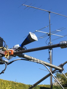
I’ve been using a Yaesu G-5500 Azimuth and Elevation rotator for the last seven years. It has been used to rotate various Yagi antennas, initially a single 9 element DK7ZB  for 144Mhz, that was replaced with 2×8 element 144Mhz Yagi antennas. Then a 67 element 1296 MHz Yagi was added followed by a Horn antenna with a modified LNB for 10 GHz rain-scatter reception.

The G-5500 is capable of rotating and elevating quite large EME arrays IF care is taken to ensure the system is well balanced. Unfortunately the balance of the array is not normally maintained as it is elevated so the elevation (EL) rotator can at times be under significant load. Quite often people forget that in addition to the antennas there’s also the weight of the power divider, the coaxial cable and Low Noise Amplifiers (LNA) which tends to make the array rear-end heavy. To try and balance my setup I added a forward facing pole with dumbbell weights to add some counter-balance weight to the front-end. This worked fine until about six months ago when I noticed that the antennas would sometimes stick on the way down. Fortunately the tracking controller I use monitors to ensure that the rotator does move when instructed to and to protect the motor it will timeout if no movement is detected. To get the array to move down I would need to elevate a few degrees up and then down. The rotator would then lower the antennas.

I tried to rebalance things by adding more weight to the front and this seemed to help… for a while.

Five minutes into the recent ARI EME contest and the elevation rotator finally failed. It failed when I tried to raise the array! After carefully checking the cabling to the rotator and then finally at the connector socket on the rotator I discovered that one half of the AC motor winding measured open-circuit. As the G-5500 rotator units have limit switches it’s possible that the fault could be either due to a faulty switch or the actual motor winding itself. I don’t believe there is a way of knowing which it is until the rotator is stripped down which is far from an easy exercise.

I needed a solution fairly quickly, the ARRL EME contest was only a few weeks away, the weather had turned and we were going through what seemed to be long spells where it was wet and windy.

Solution:

I considered the following options:

    • Repair the existing unit.
    • Replace with a new G-5500 unit.
    • Replace with a different make of rotator.
    • Use a satellite actuator.

After careful consideration I decided to implement a solution that uses a satellite actuator. There were several factors that influenced this decision, they were time to fix, hardware availability, cost, beam heading accuracy and my future EME plans.

While heading accuracy is not so critical using Yagi antennas on 144MHz this is not the case when using a dish antenna on the GHz bands. At some point in the future I will focus my EME activity on one or more of the GHz bands. Local electrical noise simply continues to rise making 144MHz EME operation very difficult at times.

Moving to a satellite actuator would hopefully provide:

    • A solution that has minimal backlash (one of the issues with many off the shelf rotators)
    • Flexibility in terms of elevation measurement.
    • A heavy duty solution.
    • Construction using basic DIY tools.
    • Lower cost.

Design:

I spent time researching online how people were using a satellite actuator to elevate an EME Yagi array / dish antenna. One of my key requirements was to have a solution that would attach directly on top of the G-5500 azimuth (AZ) rotator in the same way as the original Elevation unit. I also wanted a means of providing a direct drive (no backlash) to a device used for elevation readout. This could be a simple potentiometer or some form of encoder.


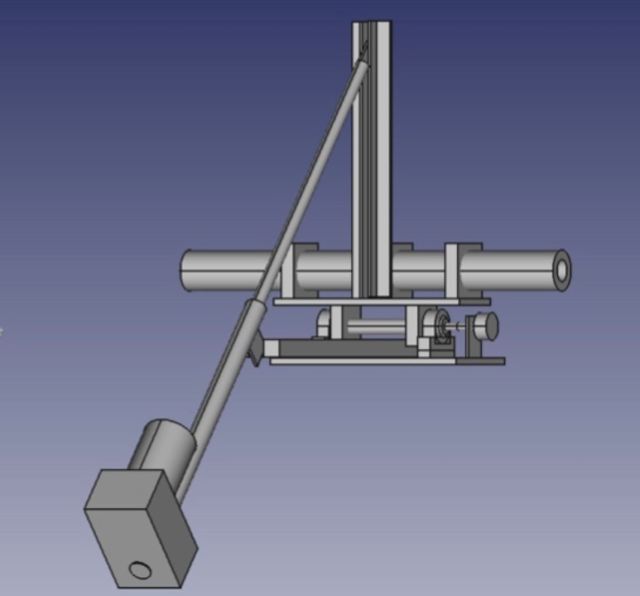
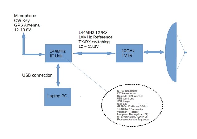
I came up with the initial design shown above. Further thought went into this along with research into sourcing suitable parts, availability and costs. I was able to source most of the material from two or three eBay sellers.

The final solution was developed with the following in mind:

    • Use of easily obtained parts.
    • No special tools required. With the exception of a bench pillar drill, the final solution was constructed using basic hand tools (hacksaw, files, tape measure etc.).
    • Easy replacement of the original G-5500 elevation rotator.
    • Direct drive of a simple 500R potentiometer or encoder for elevation readout.
    • The positioning, choice of the actuator (length of extension) and length of “push-up arm” should form an equilateral triangle when the array is elevated to 60 degrees.
    • Easily adapted for use with a 1 to 2m diameter dish at some point in the future.

Choice of actuator:

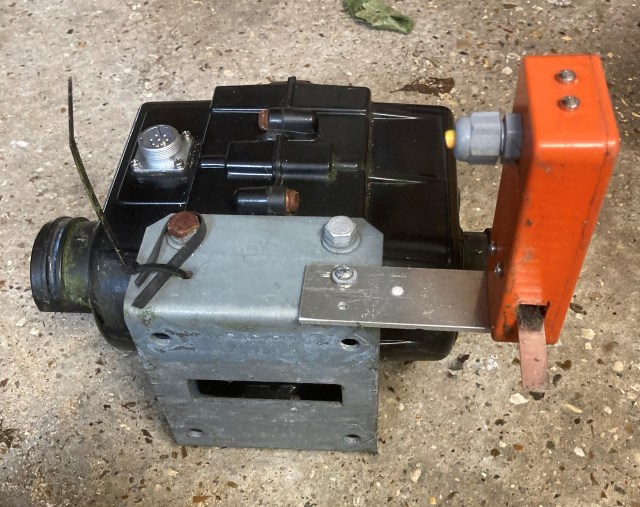
Prior to this project I had only ever seen photos of an actuator. Having researched what’s available to purchase online it became clear that there were many different manufacturers and the prices varied considerably. I’d recently read a thread on one of the EME forums where a number of well known EME operators (with very large EME antenna arrays) mentioned that they were using a genuine ScrewJack actuator. I researched this and found that they are available in standard and heavy duty versions. I decided to purchase the ScrewJack 18” heavy duty QARL3618 actuator. I ordered this late on Sunday night and it arrived on Tuesday. Now I have to confess, this really is heavy duty, it’s clearly over-specified for my current setup but it should have no issues moving a large dish at some point in the future.

Rotation Shaft:

Having looked online at lots of EME Yagi arrays that used an actuator for elevation many tend to move the actual cross-boom which rotates in some form of clamps. I considered adopting this approach but it did not offer a simple means of having a direct drive for the elevation pot / encoder and if / when I replace the Yagi array with a dish I would not have a cross-boom. I therefore decided to have two aluminium plates where the top one rotated on a 20mm solid aluminium shaft. The end of this shaft would be reduced to 6mm for the attachment of a pot / encoder.


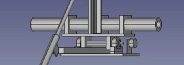
Two 20mm pillow block bearings are used to secure the shaft to the bottom aluminium shelf. Not owning or having access to a lathe, one of the challenges was how to reduce the 20 mm diameter shaft down to 6mm. I was able to do this by fitting the two bearings onto the shaft and placing them on a flat surface. Then rotating the shaft enabled me to mark the centre point on the end of the shaft. The bare shaft was then held vertically in a vice and using the mark centre-punched ready for drilling. Using a spirit level, G-clamps and vice to ensure the shaft was vertical, with great care, I was able to drill a 6mm diameter hole in the end of the aluminium shaft. An off-cut from a potentiometer shaft was then super-glued into the end of the 20mm shaft. Clearly to a Mechanical Engineer this is far from accurate but it resulted in a perfectly useable solution. As it happens I needed to extend the 6mm shaft inside the waterproof box that houses the 500R pot so I used back-to-back flexible coupler so any minute “wobble” (not that I could see any by eye) was not an issue. 

With the rotation of the 20mm shaft being used to indicate the elevation angle it must move with the upper shelf. I initially planned to use some form of clamp to fix the upper shelf to the shaft. The common “exhaust clamp” doesn’t appear to be available in such small sizes. Ideally a machined aluminium block with a 20mm hole would be used but time was against me to have these made. I considered using plastic style pipe-clamps but in the end I used two more pillow-block bearings. This resulted in a simple heavy-duty solution but of course the shaft rotated freely. To lock the upper shelf to the shaft I drilled a 6mm hole through the shelf and the shaft and used a 6mm bolt to lock the two together. The upper two bearings no longer rotate. I have greased them well and in theory they could always be used as replacements for the lower bearings should they eventually fail due to water ingress etc.

Installation:

The rotator swap-over went well although I did get caught out by a couple of “Gotchas” that I’d overlooked in my design and planning! Both related to fixing the new rotator system onto the existing Yaesu Azimuth rotator.

Yaesu use a square U-shaped piece made of thick steel to fasten the two rotators together. When I came to fasten the new setup in place I found that the original M8 bolts used to fasten the two rotators together were too short. The two aluminium shelves are a lot thicker (150mm wide and 10mm thick!) Fortunately I had a number of much longer bolts spare and was able to cut four down to the required length.

The second “Gotcha” also related to the same square U-shaped piece.

I had forgotten (well it was seven years ago!) that this had a rectangular slot cut in the bottom of it to allow it to sit flat on the top of the azimuth rotator housing. The cast Ali housing has two parallel ridges (lines) cast into it to help align the mast clamps when used. I clearly hadn’t allowed for these so I had to improvise using some extra large diameter “repair washers” to raise the new aluminium shelf above the level of these ridges.
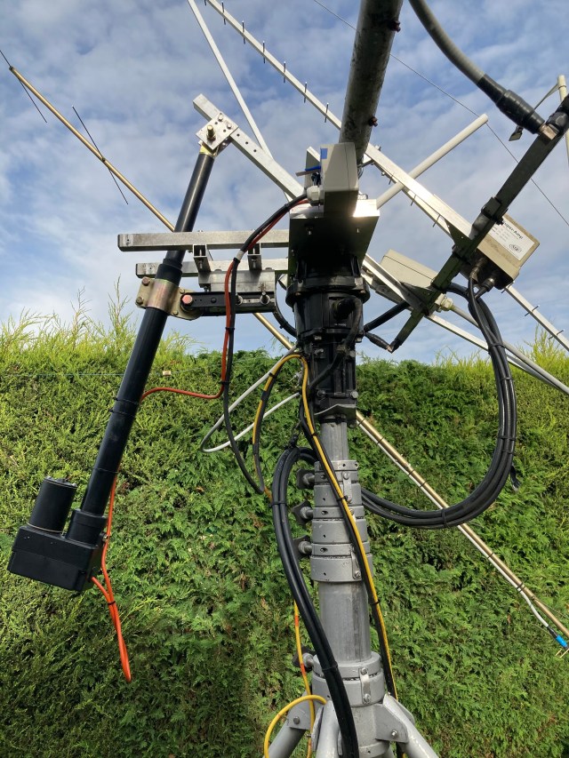
 

The final solution:


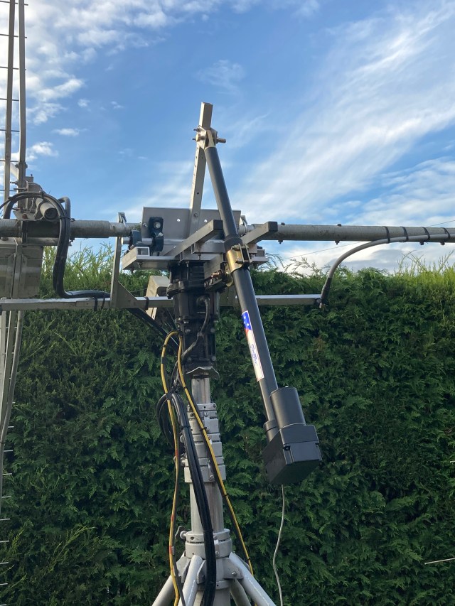
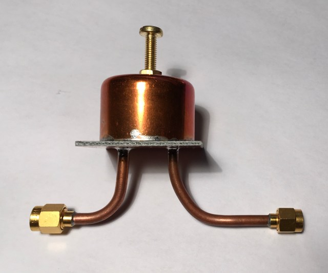
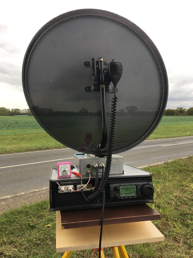
The photo above was taken during the initial testing of the new elevation system, and before the cabling was tidied!  The maximum elevation is ~ 70 degrees which is fine for EME here in the UK. 

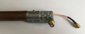
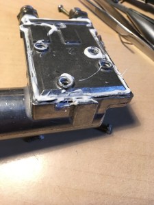
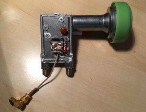
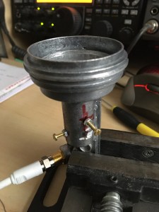
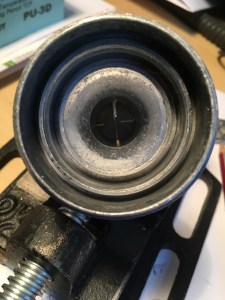
The following photo shows the waterproof enclosure positioned on the end of the rotation shaft. At present this houses a 500R potentiometer that’s used for the elevation readout.

Results:

I’m active again on EME! I mentioned earlier that time was one of the factors that was factored into my solution. I had in my mind that I wanted to be QRV for the ARRL EME contest on 10th Oct 2020 and I was, so the end result is good. I believe that I met my design objectives, and have a solution that is as good, if not better than most of what’s currently available “off-the-shelf” and at a much lower cost.

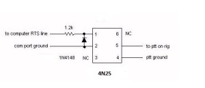
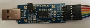
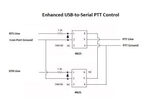
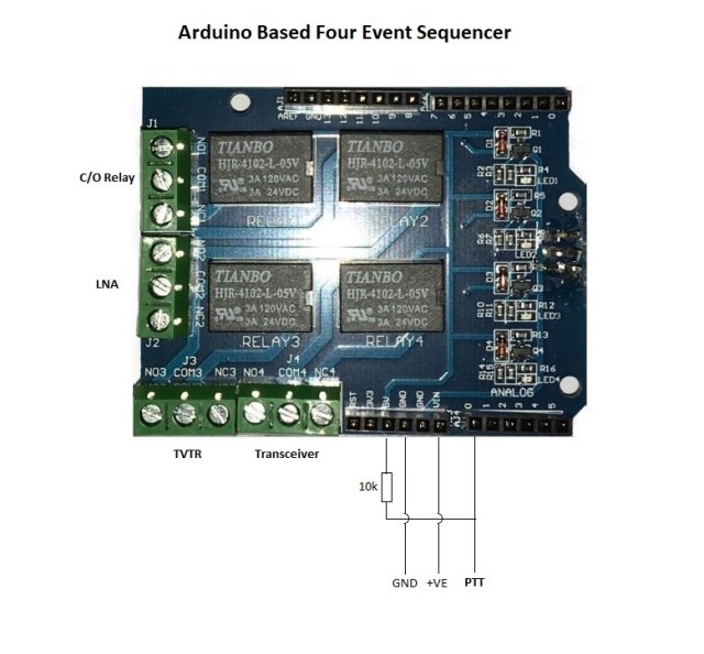
For simplicity and to get operational quickly I have the actuator auto-tracking the Moon using a simple interface board to the standard Yaesu G-5500, K3NG controller and PstRotator software.

If you do not need an elevation rotator that can “flip” your antennas up and over through 180 degrees I would seriously recommend that you consider using a satellite actuator.

Things left to do:

    • The actuator uses a DC motor which does produce some electrical noise when running. Whilst this is not bad on 2m, it is on the lower bands. I need to add some shielding and filtering to reduce this.
    • The actuator motor is currently powered by a 28V SMPS. With the voltage reduced to 25V the elevation speed is approximately 90 seconds for 45 degrees elevation. I plan to replace this SMPS with a linear power supply with PWM. This will then provide variable speed control and a reduction in SMPS noise.
    • I’m currently using a 500R potentiometer for elevation read out as this was the easiest and quickest way of getting operational. I plan to replace this with either some form of encoder or maybe a digital inclinometer.


Posted in Blog, EME, GHz_Bands | Leave a comment

QO-100 Experiments – LNB Modifications

I have been using a Goobay 67269 LNB with a small Horn antenna on 10368MHz for a while to monitor beacons via rain-scatter. This was a fairly basic setup, the Chaparral horn had been cut-off and the LNB mated to a length of 22mm copper pipe that had a WG16 flange fitted at one end. The LNB had a cover made from an old plastic milk bottle that provided protection from the rain and some limited shielding from the effects of temperature change from the wind and the Sun. This was clamped to the cross-boom of my 144MHz EME array so I had control of where the horn pointed both in azimuth and elevation. A NooElec SDR Dongle and SDR-Console were used at the shack end. This simple setup worked surprisingly well, once the LNB frequency drift settled. This frequency drift was most apparent at initial power-on and when the ambient outside temperature changed.

As I was using round pipe and 3D-printed clamps it was also easy to rotate the entire horn and LNB assembly for either V or H polarisation. This enabled me to switch to V polarisation and listen to the QO-100 satellite. I found another “hidden” bonus from this setup, I could use the satellite to check and confirm the alignment of my EME array.

For serious monitoring of beacons etc. the LNB ideally needs to be modified to overcome the inherent drift associated with the standard onboard Xtal oscillator. Like most modern PLL LNB units the Goobay uses a 25MHz Xtal. This can either be removed and the 25MHz derived from an improved source (external or onboard TCXO) or it can be left in situ and injection-locked using an external 25MHz source. There are many blog posts that describe the various ways of doing this. Two that I followed were by Andy, G4JNT and John, G4BAO. The Goobay single port LNB has lots of space around the Xtal making it easy to work on.

Here’s my modified Goobay LNB:

I recently purchased an Octagon OTLG Green twin-port LNB to use with my QO-100 system. Like the Goobay LNB I chose to use injection-locking using an external 25MHz source derived from my shack G3RUH 10MHz GPSDO. This 25MHz source will be described later in another blog post. I did not want to use one of existing twin-ports to inject the 25MHz so I drilled a small hole in the back cover directly above the Xtal solder pad. I then soldered a short length of PTFE insulated wire to the Xtal pad and that passes through the hole in the cover. A second, hole was drilled and tapped in the cover and this is used to secure a small piece of copper clad board. This board provides a ground plane for the 1k + 10nF used for the injection-locking plus a 20dB attenuator. The external 25MHz source is fed to this LNB board using a separate coax lead. All of this fits nicely on the inside of the LNB cover.


One small tip should you modify the Octagon LNB, the metal cover has 5 screws holding it in place and 3 different length screws are used. Make a note of the screw / position when taking the cover off.

With the frequency stability issues resolved the LNB unit combined with an SDR dongle and software make a relatively low-cost receiver that’s excellent for monitoring the QO-100 satellite or 10GHz microwave band.

I recently read an excellent blog post by Bob, KA1GT where he describes a low cost 10GHz EME receive setup using an LNB. He describes a number of ways to optimise the LNB. In addition to addressing the usual frequency stability issues he wrote about tuning the LNB so it’s optimised for use at ~10.4GHz rather than something like the 11.7GHz or so that the typical LNB is designed for. This optimisation is done by tuning the LNB probe(s) using a screw through the wall of the LNB housing directly opposite the probe. I decided that I would try this on a second Goobay LNB I had available in the spares box.

Here are a few photos showing the tuning screws. I used M2.5 brass screws. Unfortunately I didn’t have any brass nuts available so it’s a bit of a mix of materials which is not ideal.


A quick test using a low power 10368MHz signal source in the shack and the LNA connected to my spectrum analyser (displaying the peak at 618MHz) resulted in a noticable improvement in peak signal level as the LNB tuning was optimised by adjusting how far the screw penetrated into the housing. The next test is to set the LNB up outside on a tripod and recheck the measurements, but this time peaking on Sun noise. Even with the very basic test the results indicate that this simple modification optimises the LNB for 10GHz operation / QO-100.

More Information:

Posted in 3cms, Blog, GHz_Bands, QO-100, Satellites, SDR | Leave a comment

Enhanced USB-to-Serial PTT Interface

Many of the modern transceivers today support direct USB connectivity to your shack PC. This USB connection typically enables 2-way audio and CAT control allowing more or less full control of the transceiver, including PTT keying.

Where CAT control for PTT keying is not possible (older transceiver / software) or desired, a Serial PTT Interface is normally needed. A quick online search will show various ways of doing this. Many of the old designs will refer to the 9-pin D-style “RS232” serial connector once common on PC and laptop machines. Today we normally use the USB connector – although a hardware 9-pin port can often be added, cheaply and simply, where the PC Motherboard already has the appropriate header fitted. What’s common to both of these serial connections is that the state of the RTS line on the COM Port is used to control switching of the transceiver from receive to transmit (RX<>TX).

Here’s a typical circuit using a 4N25 opto-isolator for PTT keying:

To use the RTS line state via the computer USB port a USB-to-serial port adapter is needed. An online search for “USB serial port adapter” will show a vast number of adapters that vary in the chipset used, their size and price / availability. Based on my experience of using various adapters with a Windows OS I have found that FTDI based adapters work well.

I have used the following adapter (SH-U09C)  in my recent projects:

Caution: This adapter requires the RTS status to be inverted. This can be done very easily using the FT_PROG program from FTDI. Once this has been done the adapter simply connects to the 4N25 and it works.

Those of you who are already using this method of PTT keying will know that when you plug the USB adapter in, or boot your PC, the state of the RTS line changes 2 or 3 times which causes erroneous keying of the transceiver. Some people add a switch in the PTT line so that they can stop this happening or they have the discipline to always turn the transceiver on after they have plugged the USB adapter in or after the PC has booted.

Recently Carolyn, G6WRW posted details on Twitter showing how she had added a PTT circuit to the Pluto SDR that she was using for QO-100 operation. This PTT circuit was using the state of two GPIO pins on the Pluto to control the PTT keying. What was interesting to me about Carolyn’s design was that it prevented erroneous keying (of the PA  etc.) when the Pluto boots!

It occurred to me that the same approach could probably be used for the USB-to-serial adapter PTT keying. When a PC boots or the USB device is plugged in both the RTS and DTR lines change state several times, so in the same way that Carolyn’s design uses the GPIO state to stop the erroneous keying I could probably do the same but using the RTS and DTR lines.

Fortunately the FTDI USB-to-Serial adapter that I use has the DTR line available on an unpopulated hole on the PCB. As the CTS line is not used I very carefully cut the existing connector pin, removed the remaining piece from the PCB and soldered a link from the DTR connection to the original CTS connector pin. See photos below:

The small square pad of black insulation is there to ensure that the DTR line (red wire link) does not short to the CTS solder pad should the connector flex when connecting the ribbon cable.

The three connections (DTR, RTS and GND) from the FTDI USB-to-Serial adapter connect to the circuit above and the PTT connections go to the transceiver or sequencer etc.

Observations:

This method of using both the RTS and DTR lines has stopped all the erroneous keying that used to occur.

Many different Digi-Mode programs have been tried (WSJT, WSJT-X, MSHV, Fldigi etc.) and they all work as expected with one exception. I discovered that if the USB-to-Serial adapter is unplugged then plugged back-in and WSJT is started, when the operator commands the program to TX, both the RTS and DTR lines go High. As this is the condition where (with the new switching circuit) the PTT line should not be switched, the transceiver does not go to TX. This does not occur if WSJT-X or MSHV is used, with those programs only the RTS line goes High. Interestingly if WSJT-X is run, closed down and then WSJT is restarted, it works as expected and the transceiver goes to TX when commanded. I have experienced this on two different computers with versions 7, 9 and 10 of WSJT.

Based on my experience so far, I believe the benefits far outweigh this slight issue observed with WSJT. Clearly YMMV. If you use any software that does not manage the DTR line status correctly, i.e. perhaps both RTS and DTR are set to go high by design, putting a switch in the DTR line would overcome this issue on the occasions when these programs need to be run.

Acknowledgements:

  • Thanks to Carolyn, G6WRW for sharing her design for the Pluto GPIO PTT switching.


Posted in 23cms, 3cms, 70cms, Anglian TVTR, Blog, EME, GHz_Bands, QO-100, Satellites | Leave a comment

An Arduino Based Four Event Sequencer

When putting together a system using RF switching relays, Low Noise Amplifiers (LNA) and RF power it’s important that things are switched at the right time and in the correct sequence. This ensures that the relays do not actually switch with RF present (hot-switching) and sensitive LNAs are not damaged due to excessive input levels. The sequencer ensures that the relay has time to switch contacts before RF power is applied and things are in the correct state before the next event occurs.

My 144MHz EME system uses a W6PQL based sequencer which has worked very well over a number of years. A new sequencer was needed for my 10 GHz system. I decided to investigate the use of an Arduino to control the switching from receive to transmit (RX > TX) and then transmit back to receive (TX > RX) .

The photo above shows the end result of my sequencer project. Once again there’s nothing particularly new in what I’m describing here as far as the use of an Arduino and a simple Sketch. A quick search online will show a number of Arduino based sequencer projects. What may be of interest here, is the simple hardware used and ideas behind the construction that in its simplest form uses two modules (Arduino + Shield) and a 10k resistor.

The heart of the sequencer is an Arduino UNO and a four relay board (Shield) that fits directly onto the Arduino. The use of this Shield simplifies the overall construction and provides four switched events. The Arduino and Shield operate from either 5V via the onboard USB socket or 7 – 20V (ideally max 12V) via the power socket / Vin connector. As my 10 GHz setup uses 12V / 28V I included an additional regulator so that the small onboard regulator on the Arduino board runs with only 9V input and doesn’t run too hot. To ensure that the Arduino was not affected by any strong RF signals and also that any harmonics (noise) from the Arduino clock (16MHz) were kept to an absolute minimum all the power and switch lines are via feed-through capacitors. The complete set of parts fit nicely into a Hammond die-cast box.

Each of the four relays can switch from either a Normally Open (NO) or Normally Closed (NC) state when going from (RX > TX) or (TX > RX).

The sequencer is activated by grounding a control pin (A0) on the Arduino by either pressing the microphone PTT switch, pressing a foot-switch or in the case of PC based software via a serial controlled switch. This pin needs a resistor (10k) to PullUp when in the RX state.


Posted in Arduino, Blog, GHz_Bands | Leave a comment

QO-100 Experiments – 2400MHz Pipe-Cap Filter

Over the years I’d seen a number of projects that were using one or more pipe-cap filters. They looked as if they should be fairly simple to make so I thought I should try one to help reduce the unwanted local oscillator (LO) spur at 2256MHz (2400MHz minus 144MHz). A quick search of the Internet resulted in a number of good write-ups covering both the technical side as well as the construction of these filters.

For 2400MHz I needed a 28mm end-feed pipe-cap plus a couple lengths of RG402 semi-rigid coax, two SMA connectors, a M4 brass screw, two M4 nuts and a small piece of good double-sided PCB. The following photo shows the parts (albeit with only one nut!):

Construction of these filters is well documented on many sites so I will not repeat this information other than add one small tip: I found that that by drilling and tapping a M4 hole in the top of the pipe-cap I could use a steel screw to hold the brass nut in place during soldering. The steel screw did its job and could be simply unscrewed after soldering.

I cut the probes to a length of 8mm and spaced them 16mm apart. The PTFE dielectric of the RG402 semi-rigid cable was not removed. The photo below shows how the probes are fitted. This was taken prior to them being soldered and trimmed to length.

Once the filter construction was complete the next step was to to tune and establish the filter characteristics. I would normally do this using either a VNA or Spectrum Analyzer + Tracking Generator. Unfortunately neither of my units work as standard above 1.5GHz so I needed an alternative method. I used my ADF5351 Synthesizer and AD8317 Power Meter plus an Excel spreadsheet. This is the test setup:


Using these two devices it was very easy to tune the filter for minimum insertion loss (IL) at 2400MHz. Then with a simple press of the 10MHz step button (many times!) it was easy to step through from 2200MHz to 2600MHz and record the power meter reading in a spreadsheet and plot filter response curve. When I constructed the power meter I also included a socket that allows me to connect an analog volt meter to show the AD8317 Vout voltage. It’s far easier to tune for a minimum or maximum reading using an analog meter rather than the standard LCD display.

What was also a very interesting exercise was to compare the filter characteristics when using a steel screw in place of the brass tuning screw.

Using the brass tuning screw is clearly the better choice giving much steeper skirts and 25dB rejection at the LO frequency (2256MHz). Also the IL was approximately 1dB compared to 2.4dB when using the steel screw.

For more technical information on pipe-cap filters see: Pipe-Cap Filters Revisited by Paul Wade, W1GHZ

Posted in Blog, GHz_Bands, QO-100, Satellites | Leave a comment

QO-100 Experiments – 2256MHz Local Oscillator

I chose to use an ADF4351 based synthesizer module to generate the 2256MHz local oscillator (LO) needed for my QO-100 QRP  transmit converter. This is controlled by an Arduino Nano. Having already used one of these modules for the 54 to 4400MHz synthesizer based signal generator. Once again I used an Arduino sketch written by F1CJN, this one being the single frequency option developed for QO-100 use.

Like many of my smaller projects, copper-strip board formed the base for securing the modules and providing the inter-connections, level-shifters and so on. A tin box was used to house and screen the LO with the supply voltage fed via a feed-through capacitor. These steps being done to try to ensure the desired output was as clean as possible.

The photo above is a screen capture from my Rigol DSA815-TG Spectrum Analyser (SA). As standard this model has a maximum frequency of 1500MHz. To check the output of the LO synthesizer running at 2256MHz, I used a passive RF mixer plus my second ADF4351 signal generator running at 2000MHz to produce an input to the SA at 256MHz (2256MHz minus 2000MHz) Whilst the actual dynamic range of this solution has not been measured and calibrated against better equipment it is sufficient to enable me to get an idea of what is going on.

Posted in Blog, GHz_Bands, QO-100, Satellites | Leave a comment

QO-100 Experiments – QRP Transmit Converter

Having spent some time listening to the QO-100 satellite using the Goonhilly WebSDR facility and my own temporary receive solutions, I decided it was time to try generating some RF and get a signal up to the satellite.

I was aware of stations transmitting using a number of 2.4GHz based modules available on various websites such as eBay. This looked an interesting approach and the modules could probably be repurposed if things didn’t work out or I decided to adopt a completely different route.

I decided to purchase the following modules:

This is a fairly conventional transmit converter setup. I did however want to use 144MHz as the IF rather than 432MHz. The reason for this being that I already have a GPSDO locked low power 144MHz IF setup that I use with other transverters. This choice of IF would mean that good filtering would be needed to ensure that the final output on 2,4GHz was acceptable and any unwanted spurs were well down on the wanted signal.

This photo gives an idea of the basic setup that has evolved so far:


If we follow the RF route, things start off with a 10MHz GPSDO derived source being input to the tin-box on the left. This box houses an Arduino Nano and the ADF4351 synthesizer board. This produces approximately +4dBm output at 2256MHz which is fed into the ADL5350 Mixer module. In addition to the 2256MHz input (via blue coax cable), 144MHz is input at +15dBm on the spare unterminated SMA socket. This results in the wanted 2400MHz output which is then fed into a 2400MHz BPF (bandpass filter). The output of the BPF is then fed via the long semi-rigid length of coax into a SPF5189Z Low Power Amplifier. These amplifiers seem to have a gain of typically +10dB. The output of the first amplifier is then fed into a homemade 2400MHz pipe-cap filter and then finally into a second SPF5189Z.

This current setup is at present far from being optimised in terms of physical layout and minimal losses. As a result of the numerous SMA connectors / adapters / interconnecting cables and filtering the final output power is approximately +7dBM (5mW) but it’s an acceptable 5mW at 2400MHz with all spurs as best as I can tell >55dB down on the wanted signal.

To be continued…

Posted in Blog, GHz_Bands, QO-100, Satellites | Leave a comment

Fun on 10GHz – 2 ‘Rain-Scatter’

I’m still what some might call a novice when it comes to the 10GHz band. It’s a band that’s like no other that I’ve operated on, and I’m hooked on it. I’ve recently discovered first-hand the effect of rain-scatter at 10GHz and gained a small insight into what this fascinating propagation can offer.

Most of my 10GHz activity is done operating /P (portable) from a local site just over 5 minutes’ drive from my home. It’s not a particularly high spot but it has reasonable take-off from SW through to N. In all the times I’ve operated from this site I’ve never had much success in hearing things towards the East. At least not until a few days ago when the ON0EME beacon appeared via rain-scatter. This beacon is located in Belgium and is ~300km away. The following screen grab shows the Doppler effect (~100Hz spread) on the signal.


As my 10GHz equipment is all tripod mounted (i.e. sits about 1m above the ground) when it is setup at home in the garden, other than pointing up at the sky, it’s impossible to have a clear take-off in any direction due to either buildings or hedges.

My /P setup is not weatherproof and yesterday it rained on and off for most of the afternoon. It was also the second day of the RSGB UHF / Microwave contest. As I couldn’t operate outside I thought I’d try setting the gear up indoors, open the patio-doors, and point the dish up towards the dark rain clouds. Hoping that I might hear my nearest beacon (GB3PKT, 10368.945MHz) which is vaguely off in the direction of those clouds.

With the dish elevation set to about 5 degrees, I proceeded to slowly sweep the maximum arc possible out through the patio-doors. Doing this for a few minutes produced nothing. I then decided to point the dish up at about 20 degrees. To my surprise GB3PKT trace appeared on the screen, a tweak of the AZ / EL and it was audible! Here’s a screen grab showing the Doppler effect (~200Hz) and JT4g decode.

With everything peaked for GB3PKT I wondered if I might “see” any other beacons, so with the IC-706 Panadapter running I proceeded to click through the beacon frequencies (pre-loaded in the radio) and much to my surprise GB3LEX appeared! Now this really was a surprise (at least to me it was) as this beacon is ~157km away and the normal dish bearing should be ~312 degrees. My dish was currently pointing at ~60 degrees. Here’s a screen grab of the GB3LEX on the Panadapter:

Unfortunately this only lasted for about 5 minutes and then the sky brightened up and tests came to an end.

The following two photos show normal antenna bearings for GB3PKT and GB3LEX respectively.

I’m looking forward to doing further rain-scatter tests, and the possibility of making contacts on 10GHz from home via this fascinating propagation.


Posted in 3cms, Blog, GHz_Bands, Mobile / portable Operation | Leave a comment

Fun on 10GHz – 1

Over the last 20 years or so I’ve rarely operated my radio equipment away from home. This has changed since I’ve caught the “microwave bug” and got started on the 10GHz band.

My 10GHz setup comprised initially of just a DB6NT Transverter (TVTR) and an IC-706 transceiver for the 144Mhz IF side plus a dish or horn antenna. I soon learnt that in addition to these core items there are a number of additional things that can help to maximise your contacts and results on the band. Frequency accuracy, timing, digi-modes, SDR waterfall display, CAT control etc. can all help, especially if you’re intending to develop your setup for EME operation.

Adding a lot of these ancillary items meant that there were lots of things to remember  when heading out to operate at a portable (/P) location. I wanted a solution that was easy to setup and take-down, didn’t need to have lots of cables plugged in each time and had minimal risk of me forgetting a vital item. I decided that all these additional items should ideally be housed in one enclosure.

Searching for a suitable enclosure resulted in me repurposing an old Dell Optiplex 775 PC case to house all the various bits and pieces. I now have one neat enclosure that houses the following:

  • IC-706 Transceiver
  • PTT break-out box
  • Digimode / CAT interface
  • USB sound card
  • SDR dongle
  • USB hub
  • LeoBodnar GPSDO providing 10MHz and 30MHz output for TVTR and IC-706.
  • 10dB 30W RF attenuator
  • Wilkinson RF splitter
  • Low power Dummy-Load (DL)
  • RF switching relay (SDR / DL)
  • Four-event Arduino Sequencer

The following diagram and photos show the interconnections and end result.


At the time the above photo was taken, the rear panel had not been finished. As a result the 144MHz, 10MHz, RX/TX switching and power interconnections were on fly-leads out of the front.

This enclosure with the IC-706 transceiver and ancillary bits is now working really well.  It can also be used as the IF for other bands, for example, 23cms where I use a SG-Lab TR1300 TVTR or with an HF antenna on the lower bands for low power (QRP)  propagation tests which is another area that I’m interested in. The single USB connection to a PC allows for software control of the radio. WSJT-X is a program of significant interest as it provides automatic Doppler shift correction for EME communication. The use of the old PC case has worked out surprisingly well.

What’s next…

  • Currently the interconnections between the 144MHz IF unit and the 10GHz TVTR housing uses three individual cables. I have two multiplexer units to construct which will enable the 144MHz, 10MHz and RX/TX switching all to be done via one coax cable. This plus a (12 – 13.8V) power cable will make for much easier installation, especially if mounting the 10GHz TVTR section at the top of a mast.
  • Improve the tripod table and elevation adjustment.
  • Improve the dish fixings (note the slight lean to one side in the above photo!)
  • Get out and operate /P as much as possible and to try to encourage more use of the GHz Bands outside of contests.


Posted in 3cms, Blog, EME, GHz_Bands | Leave a comment