Fun on 10GHz – 4 ‘AD8307 Based Noise Meter – 144MHz IF’

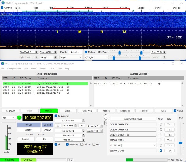
My small (~ 65cms) dish 10GHz EME experiments have been great fun. More information can be found here. The next step is to install a larger 1.2m off-set dish. This will initially use my existing AZ / EL system, the AZ side will need to be upgraded as soon as possible. With the inability to track the Moon accurately i.e. typically in 0.1 degree steps or better, I’m going to have to manually “nudge” the dish to keep the moon in the “bore-sight”. To help do this some additional aid is needed, and this is where the noise meter comes in. It can also be used to optimise and validate the performance of your feed, dish and overall receive setup.

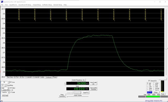
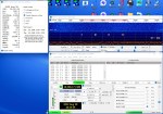
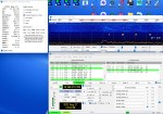
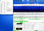
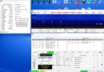
To the best of my knowledge a noise meter hardware solution cannot be purchased “off the shelf”. For a software solution SpectraVue can be used in Continuum mode. This will also provide hard-copy of your system performance. I have been using SpectraVue with good results.

So why go to all the bother and expense of making a noise meter? It’s primarily to have a good old fashioned analog meter that will clearly indicate noise peaks, it’s also an instrument that will work both indoors and outdoors, not require a computer, connect directly to the transverter IF output, give a clear visual indication to help track, optimise and measure the performance of my EME system(s).

Searching the Internet highlighted three main sources of information published by VK5BZ, G4NNS and DB6NT. Having read most of what I could find I decided that I would build a unit adopting ideas from these main sources. I wanted a unit that would:

  • Be modular, i.e have separate RF frontend amplifier with a detector plus metering backend.
  • Work with both 28MHz and 144MHz transverter IF outputs.
  • Incorporate Receive / Transmit switching to protect the RF amplifier devices and detector board.
  • Operate off 12v – 15V so that a battery can be used outdoors.
  • Allow for additional Band Pass Filters (BPF) if needed.
  • Provide detector voltage output for an extra large external meter.
  • Possibly incorporate a switchable attenuator for self checking.

This resulted in the following two board designs:

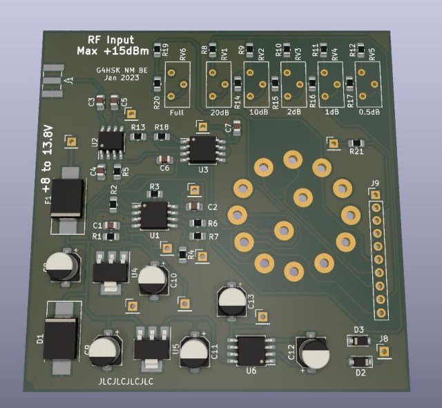
Noise Meter RF Amplifier Board

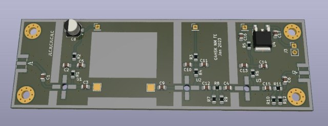
Noise Meter AD8307 Detector and Metering Board

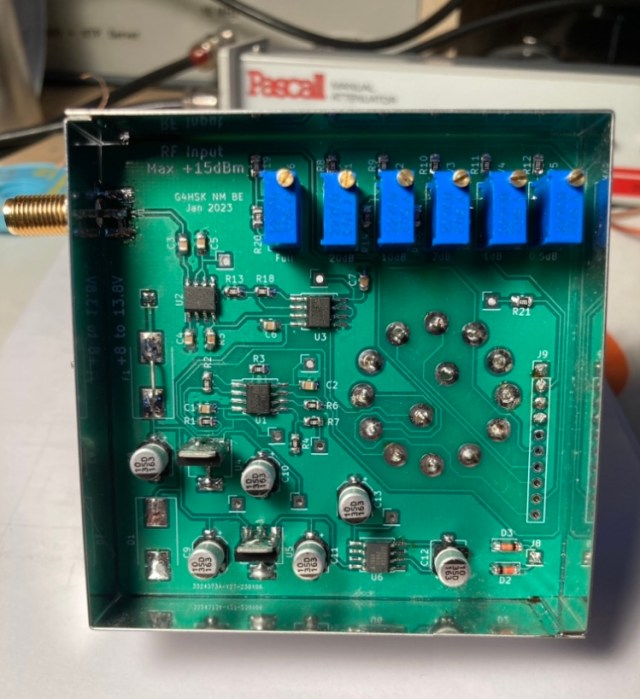
This was supposed to be a Xmas holiday project. The board designs were started but not finished! They were sized to fit the “German tin plate boxes” that are popular amongst microwave constructors. If I’m honest in the end I did rush things a little once I realised that they were still not finished and Chinese New Years celebrations would soon be upon us. I usually finish a board design, park it for a week or so and then revisit to check and spot any “undocumented features”. This method of error detection seems to work, needless to say with the time constraint I did not do this and when I came to build the boards I dicovered that I’d I messed up the two voltage regulator footprints on the detector + metering board!! Fortunately the current drawn is very low and I was able to mount the devices vertically “standing up on their legs”.

Here are the two finished modules:

Noise Meter 144MHz IF Amplifier Board

Completed AD8307 Detector and Metering Board Underside

Completed AD8307 Detector and Metering Board Topside

The RF Frontend board is for 144MHz IF, it uses 3 x MAR-8A+ devices and produces about around +80dB gain. With -100dBM input from the spectrum analyser tracking generator the Band Pass Filter (BPF) response looks something like this over a 500MHz span:

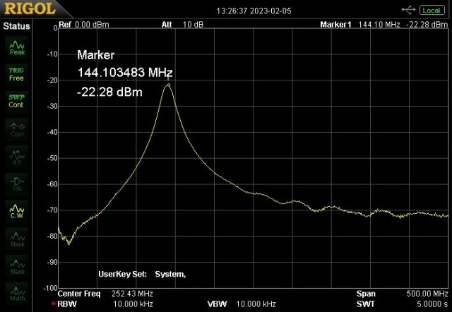
144MHz IF Amplifier Onboard BPF Response


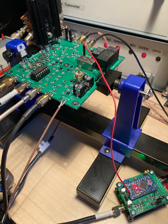
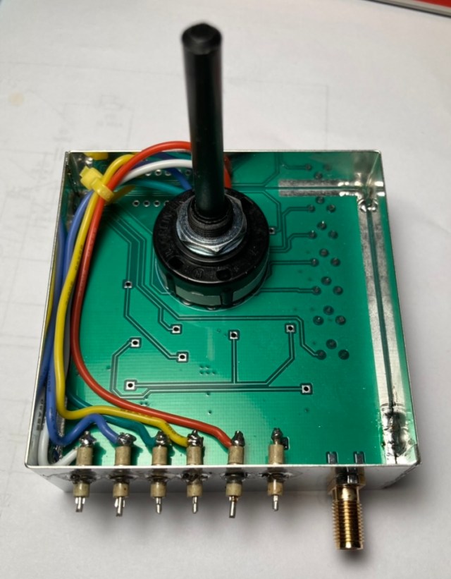
The completed modules being tested:

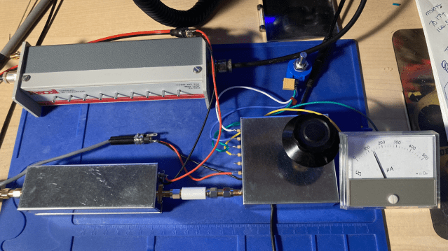
I’m currently using the modules as shown in the photo above. They will eventually be housed in a suitable enclosure along with the extra modules to protect the unit when transmitting plus a 28MHz frontend board.

The noise meter appears to work as expected. Tests with switched attenuators inline before and after the frontend amplifier module suggest that both the detector and metering stages are working correctly and levels are well within the optimum input range of the AD8307.

Using the “standard” VK3UM EMECalc software to calculate the expected Sun and Moon noise from my setup I can see that my setup is working as expected, I’m currently able to measure 4dB of Sun noise. With such a small dish measuring Moon noise is more of a challenge, measurements so far done when the Moon was near maximum elevation and the dish dish pointing away from roof tops indicated ~ 0.1dB of Moon noise.

Lessons learnt:

  • Don’t rush boards and double check component footprints!
  • Think more about the positioning of any inter-stage screening.

Things to do next:

  • Purchase a suitable enclosure.
  • Construct 28Mhz Frontend.
  • Incorporate Receive / Transmit switching (protection).
  • Possibly incorporate a switchable attenuator for self checking.

Acknowledgements:

  • VK5BZ for his excellent article describing his noise meter.
  • G3NNS for his excellent article describing his noise meter.
  • DB6NT for his excellent article describing his noise meter.


Posted in 23cms, 2M, 3cms, 70cms, Blog, EME, GHz_Bands | Leave a comment

Fun on 10GHz – 3 ‘EME Experiment’

The prolonged hot and dry spell that the UK and most of Europe has experienced has meant that there’s been no rain to enhance the capabilities of my small 10GHz home setup. My small dish only has a clear take-off between approximately 230 – 360 degrees which is fine up-country but to receive anything in any other direction, particularly to the East I need good rain scatter / backscatter.

The lack of anything really new happening on the band got me looking at ways to improve my station. My ultimate goal on 10GHz has always been EME. Having read about the success a couple of stations have been having with a 1.2 metre dish I decided to see what I could hear using a smaller dish I had gather dust in the shed.

My current setup was using a very old PW Dish with a Penny-Feed. The “new” dish would be an aluminium perforated off-set dish (Lenson Heath 60) with a  new feed horn. I’d heard that good results had been obtained using the Chaparral front section off an LNB mated to a piece of 22mm diameter copper pipe with an SMA transition. It just so happened that in my box of “bits not to be thrown away” I had the front section off a Goobay LNB plus the 22mm section.

I soon had a new feed put together ready for testing.

The next step was to get the feed positioned correctly. With the new dish fixed in place and a 3D-printed clamp to hold the feed horn, as a starting point, I simply positioned the feed to where I expected a standard LNB and clamp would normally be.

Sun noise can be used to establish how well a dish and its feed are performing. In very simple terms the concept is point the dish at the Sun, record the noise level, then point the dish at a cold part of the sky and the difference in measured noise level gives an indication of how well your system is working. There are many excellent articles online that explain all of this in great detail, also software where you can define your system and it will calculate an expected level of noise. For more information look here.

I was keen to see how well things were working, based on what I’d read people were reporting figures of around 6dB Sun noise for an 85cm dish so my expectation was that I should see around 4.5dB of Sun noise using my 65cm dish. Clearly there are many things that can affect this measurement.

My first tests were encouraging I was seeing a little over 3.5dB of Sun noise.

To ensure that what I was measuring was meaningful I used a stepped attenuator between output of the transverter and the input to the K3. By attenuating the input to the K3 in 1dB steps I could check that the measurement seen in SpectraVue did the same.

While doing all of this I realised that there was an EME contest coming up where hopefully a number of large 10GHz capable stations would be active. So if I was able to receive the 10GHz EME Beacon, DL0SHF located in Germany I should stand a chance of decoding some actual EME contacts taking place.

One of the first things that became evident in doing the Sun noise checks was that pointing the dish accurately was not easy! Even with this very small dish (most 10GHz EME stations use a dish upwards of 1.2m in size) 1 degree of azimuth movement would see the signal level fall away. Once the dish is aligned on the Sun / Moon you then need to track its movement. I had used my azimuth and elevation tracking system previously on 144MHz and 1296MHz EME with Yagi antennas where the system was more than adequate. The dish however was a totally different thing.

I spent several hours over a number of days tracking the Sun (peaking on noise) and drawing up a calibration table for my rotator system. I got to a point where using my calibration table I could point the dish and be within a degree or so.

The next step was to try and decode the DL0SHF beacon. At this point I knew my receive setup was working okay (but not optimised) but in addition to that there were three other key requirements:

  • Accurate measurement and control of dish azimuth heading.
  • Accurate measurement and control of dish elevation heading.
  • Accurate frequency control and ability to manage Doppler shift.

The first two requirements were not ideal but should get me close 🙂 the third was fine as the K3 was able to do full Doppler tracking in 1Hz increments.

At the time of trying the Sun and the Moon headings were fairly close. For me this was both good and bad, it meant that there was more noise overall, the degradation was also fairly high but it also meant that I could check the dish alignment by first peaking on the Sun noise and then rotating the dish just a few degrees to where the Moon should be. After half an hour or so I got my first decodes from DL0SHF at around -20dB.

To receive DL0SHF your receiver should be tuned to 10368.024MHz and the Doppler auto tracking (in WSJT-x) set to “On DX Echo”. This should place the signal around 1000Hz. I seem to decode it approximately 50Hz high.

Over the next few hours I tracked the Moon manually and continued to successfully decode the beacon.

The best signal strength I managed was -17dB.

At the time another station using a 1.2m dish posted a report of around -11dB so I was not way off what was to be expected for the size of dish I’m using.

Next was the EME contest. Who would I be able to decode?

The first station was OZ1LPR, I checked the beacon first and then tuned to his frequency.

I decoded three other new stations, GB2FRA, DL0EF and W3SZ. Here are some screen shots of the activity decoded (click on image to enlarge):


Clearly all those stations were running large dishes and high power so all credit goes to them, but it was still a great buzz to see those decodes on my side. What was also surprising was that they were mostly audible in the loud speaker and not just visual on the computer screen.

The hardest part of this journey was tracking the Moon with my current system. A larger dish would make it even more difficult. I decided to change my tracking system software to work to 0.1 decimal places and recalibrate both azimuth and elevation followed by an extended period tracking the Sun. Just to get a good baseline to build upon.
I was pleasantly surprised, I was able to track within 1dB of maximum Sun noise. Now clearly this is still with a small 65cm dish. Going to a 1.2m dish would result in a much greater variation.

The above image shows the Sun being tracked (for maximum noise) over a 2.5h period and with a maximum deviation of 1dB.


Key lessons learnt?

  • Fun can be had monitoring EME with a small dish setup.
  • The new Chaparral feed horn seems to work well.
  • Acurate tracking of the Moon / Sun is hard. Azimuth being probably the most difficult.
  • Any backlash in the rotator system is bad.
  • You should aim for 0.1 degree or better tracking accuracy.
  • Having accurate frequency control (GPSDO) is a must.
  • Being able to track Doppler shift automatically is a major bonus.

What’s next?

  • Improve the rotator / tracking system.
  • Optimise the position of the feed horn.
  • Weatherproof the feed assembly.
  • Get a bigger dish!


Posted in 3cms, Blog, Elecraft K3, EME, GHz_Bands | Leave a comment

QO-100 Experiments – Maclean MCTV-670 LNB

I was asked recently which LNB is most popular with QO-100 users and is the easiest to modify to improve frequency stability. Several “off the shelf” names sprang to mind, they’re often advertised as TCXO controlled or PLL suitable for modification but as far as “most easily modified” I struggled to answer that as it’s dependant on one’s skills, experience, workbench facilities and own perception of what’s easy vs difficult.

I have modified two types of LNB for 25MHz reference-locking. They were single and dual-port devices from Goobay and Octagon respectively. Of the four that I’ve modified one had to be scrapped as I managed to accidentally damage the PCB! Otherwise they all performed as expected after modification.

So what are the typical “hands-on” i.e. practical challenges when trying to reference-lock an LNB with an external frequency source?

  1. Having the right tools.
  2. Getting the thing apart.
  3. Feeding in your frequency reference signal.
  4. Working with very small Surface Mount components.
  5. Getting it all back together and ensuring it’s still weatherproof.

Like with most things, there are invariably several different ways to achieve the same end-result, and each way will possibly present different challenges.

I wanted to modify another LNB for use on 10GHz so this led me to look at what people are currently buying and modifying for QO-100 use. My requirements were:

  • Two port LNB.
  • PLL with standard 25MHz crystal.
  • Simple reference-locking while retaining the original crystal.
  • “Easy” to modify. 😉

During my online research I came across a section on the QRZ.com page of PA2JSA titled “QO-100:  Simple LNB Modification”.

I decided to buy a Maclean MCTV-670 from Amazon UK and it arrived in just under 5 working days.

The plastic casing was easy to remove, first step is to remove the red coloured rectangular shaped part that slides down to protect the F-connectors, then carefully open the two halves of the main LNB body. Do not remove the front red cover.

The next step is to remove the white sealant used to waterproof the two sections of the alloy housing. I used a number of wooden cocktail-sticks to do this. Being of softer material and with sharp points they removed all the sealant without any damage to the alloy cover. This then exposed five Torx-headed screws.

I was careful to remove and place all of the screws down in the same position / pattern that they were fitted, just in case one was a different length. I got caught out with a previous LNB that I took apart. Fortunately this time all five screws are the same length.

Once all the screws have been removed the cover needs to be removed. Care needs to taken here as the LNB PCB is only kept in place by a small locating pin and the soldered connections to the two F-connectors. It’s possible that there may be a small amount of sealant between the underside of the cover and the PCB. You do not want to pull the PCB up when removing the cover. I worked from the connector end and used a thin piece of plastic to gently  “lift” the cover off.

The overall physical design of the LNB is ideal for this modification. The upper most F-connector can easily be disconnected from the PCB and the way the screening walls on the underside of the top cover run it is very easy to route a thin wire from the 25MHz input port to the 25MHz crystal input lead of the RT320M Chip.

I used a 1nF 0805 surface mount capacitor and a short length of PTFE insulated wire to make the connection to the point on the PCB. This is described in detail on PA2JSA’s QRZ page. Soldering the wire to one end of a very small surface mount capacitor does require a very small tipped soldering iron, good lighting and eyesight plus a steady hand. This solder connection is the hardest part of the modification. The photo below shows the completed under the cover modification.

Looking closely you can also see some small dabs of epoxy-glue used to hold the wire and capacitor in place.

Once the modification was done I replaced the cover without any sealant and tested the LNB.

The next two photos show the LNB receiving a GPSDO signal source on 10368MHz in standard PLL form without any external 25MHz locking and then with 25MHz reference-locking. The 25MHz input to the LNB was from my downconverter which has a 10MHz GPSDO input. I found the optimum level of 25MHz input to be around -20dBm.

The test results were as expected so the LNB cover was sealed with neutral cure (non-smelling) silicone sealant. The outer plastic casing was then clipped back into place.

Labelling of the two F-connector ports completed the simple modification of the LNB.


Update(s):

  • See Here for further info on this LNB.

Acknowledgements:

  • PA2JSA for his QRZ page.


Posted in Blog, EME, GHz_Bands, QO-100, Satellites | Leave a comment

QO-100 Experiments – 2.4GHz UMTS PA

I spent a long time looking at the various power amplifiers being advertised for QO-100 use. My ideal unit being one that could be used for both QO-100 and normal 13cm terrestrial operation down at 2320MHz. It could be a kit, an off-the-shelf unit or a surplus unit requiring modification but one with a proven documented method to make it work.

I settled on an ex-UMTS power amplifier board that was being sold on eBay. It ticked all the boxes, the price was extremely attractive and most importantly for me it had a well documented modification process by SP8XXN and SP5MU.

The parts arrived very quickly and were exactly as described. I’d downloaded the modification instructions and quickly read a few other related posts on various forums. The hardest part I could foresee would be mounting the PCB to a suitable heat sink. The two LDMOS type BLF7G22L-130N devices and the circulator on the output sit below the bottom surface of the PCB so ideally three recesses need to be milled into the heat sink. Not having access to a milling machine I decided to use a thin sheet of copper with suitable cutouts to allow everything to sit flush on the heat sink.

The photo above shows the thin copper sheet “gasket”. Great care was taken deburring all the holes and cut-outs.

The heatsink was marked up, drilled and tapped and the various parts of the power amplifier were assembled.

This slideshow requires JavaScript.

With a 50 Ohm load attached to both the input and output I applied a reduced voltage (22V) supply to the board. No magic smoke escaped but the board was immediately drawing over 4A! It appeared to be self-oscillating, I assumed that this was most likely due to earthing issues. I removed the PA board from the heat sink to check the surfaces and component levels with the straight edge of a ruler and discovered to my surprise that each of the power connectors had two very small plastic locating pegs that protruded beyond the bottom surface of the PCB. I had missed these four protrusions!

The two red circles show where the four plastic locating pegs are.

I very carefully trimmed those back and made sure they would no longer cause a gap between the underside of the PCB and the copper sheet / heat sink. I was also concerned that the carefully hand lapped surface of the old second-hand heat sink would not provide good enough earthing so I decided to add a second sheet of copper to provide a better conductive surface.


The PA was reassembled and retested, this time the quiescent current (680mA) was much closer to that expected.

My goal was to achieve a maximum output power of around 20W – 25W but to run the amplifier at just 4W to 5W output when operating in the narrow-band segment of QO-100. The various online notes offered varying levels of change to improve the efficiency and power output at 2.4GHz. Some of the changes described were to alter certain tuning tabs, removal of the circulators and changing the bias circuit / class of operation. I wanted to make the minimum number of changes. I decided to initially just remove one capacitor on the input and modify the matching of each transistor as described here.

The input and output matching of each device was adjusted slightly by adding / removing copper foil and with these modifications, with the amplifier still operating in Doherty mode I was able to measure ~31W output into a 50R dummy-load for around 2W input.

Having got this far the next challenge was to work out how to switch the PA “off” on receive. Again reading online there seemed to be two approaches to biasing the PA.

  • Where the PA was to be kept pretty much standard (Doherty) it seemed the common approach was to either switch off the 28V supply to the entire PA board or just to the bias circuit on receive.
  • If the objective was to use the PA for DATV (where much more output power is needed) the common approach was not to use the onboard bias circuit and add a new switched bias supply board.

Thanks to the hard work by G8UGD and his posts on the Amsat-DL forum I was able to get a schematic of the onboard bias circuit. In fact most of what I experienced the hard way in my build was already well documented on the forum. I shared this schematic with a uW ELMER and asked for his advice on how best to switch the PA “off” on receive.

For my use, I was recommended to retain the original Doherty biasing as this offered additional functionality such as temperature tracking. It was suggested that I short the junction of the 13K5/1K (marked 3V75) to ground via a 1K resistor, this would cut-off both bias supplies and drop the bias voltages below cut-off.

Section of Bias circuit showing where to add control line.

I added the 1K resistor as suggested, this is switched to ground on receive by a relay on my homebrew upconverter. I also 3D-printed some guides to help secure the 28V connections to the amplifier PCB. This completed my modifications, and the end result met with my requirements.

I am currently using the PA on the narrow-band section of QO-100. It runs with the DC supply set to ~24V and drive levels set for a maximum of 5W output. With the fairly long run of coax I have to the dish feed and a 95cm OS dish my signal is typically 6dB down on the beacon which I find to be ideal.

The end result is a PA that is not exactly small in size or especially efficient but it serves my needs. It was not expensive and provided a good learning curve, plus it can still have additional modifications made to improve the maximum output power and efficiency if ever needed.


Posted in Blog, GHz_Bands, QO-100, Satellites | Leave a comment

Yaesu FF-501DX Low Pass Filter

I purchased the FF-501DX LPF along with a number of other items. It belonged to a very good friend, sadly it was part of his SK sale! As my interests are very much VHF upwards, along with the odd session on 10m, this LPF has sat gathering dust for the best part of four years now. With conditions improving and the ES season well underway I’ve been more active on 10m and this got me to look at the FF-501DX LPF again.

There was no paperwork with it so I had no idea of the specification. It has a cast alloy housing, weighs a reasonable amount and has the dreaded SO-259 connectors (it is HF  🙂 )

Curiosity got the better of me and I had to take a look inside…

I have to say I was impressed with the build quality.

The next step having reassembled it was to see what it looked like on a spectrum analyser with tracking generator.

FF501DX Filter Characteristics

The results were equally impressive.

I then looked at the Return Loss / VSWR using an early version of the NanoVNA. The LPF was connected directly to a Bird 50R dummy load.

I added markers for 3.5MHz, 14MHz and 28MHz and did a sweep from 1MHz to 30MHz.

VSWR 1MHz to 30MHz

Overall the results were much better than I had expected.

In summary I measured:

Insertion Loss:   Less than 0.2dB

Cutoff:   35MHz

Attenuation above 70MHz:   Better than 80dB

Return Loss:   Better than -24dB

Searching for “FF-501DX LPF” on the Internet returned what seemed to me to be surprisingly few results. It did however produce a single link to a copy of what appears to be the original one-page information sheet, which can be found here. I also found a copy of an old radio magazine from 1985 that was advertising the FF-501DX for the sum of GBP33.00

Comparing my results with the original specifications shows that I have a good one here. Not that I would expect anything different from my old pal, although thinking back, he was the founder of the 30 Volt Club!   🙂


Posted in Blog, IC-7300, IC-735 | Leave a comment

AD8317 + Arduino RF Power Meter # 2

I built an AD8317 power meter a couple years ago. The AD8317 is specified for operation up to 8 GHz, but it provides useful measurement accuracy over a reduced dynamic range of up to 10 GHz. With suitable software and calibration this module can provide a very useful piece of test gear for the shack.

My own test equipment doesn’t provide any means of accurately measuring power levels above 1.5GHz and unfortunately I’ve not yet been able to attend a MicroWave Round Table event. For those of you that have never attended such an event, one of the many highlights is usually some form of test facility that typically offers frequency / power measurement, spectrum analysis etc. Hopefully we will all soon be in a position where all these excellent events will be able to run again.

My interest in QO-100 and a homemade up-converter meant that the need to do power measurements at 2.4GHz was growing. This seemed a common requirement amongst a small group of fellow QO-100 enthusiasts. As a result of this and the successful completion of another recent project, where five of us constructed a 50MHz Power Reference Source, this new project came about.

This project is based on the PA0RWE Milliwatt Power Meter design and incorporates the W1GHZ Simple RF Power Reference module.

My recent interest in KiCAD resulted in the following PCB:

The PCB has the Arduino Nano, the AD8317 module and the 50MHz Power Reference board attached to the underside. Once again the PCB was designed to have duplicated footprints so that the builder can choose to use SMD or leaded components.

The PCB is a shoehorn fit into a Hammond enclosure. I have to confess this was more by luck than judgement. One of the things I have learnt very quickly is to give careful consideration to the size and type of enclosure you intend to use and where the fixing holes etc will go. Some 3D-printed supports were produced to hold the PCB in place and support the LCD display. Bulkhead N to SMA adapters are used for the RF in and out connections.

This slideshow requires JavaScript.


The following photo shows the underside of the completed Power Meter.

Three power meters have been built so far, two are complete and one is awaiting the metal bashing to be done.

Incorporating the 50MHz Power Reference has proved to be very useful for doing basic (albeit at a low frequency) checks of attenuator values, cable continuity / losses.

I have been able to calibrate the power meter up to 23cms using my Rigol SA and for the 13cm band the best I’ve been able to do is to calibrated using the output from my ADF4351 signal generator. Unfortunately I’ve still not been able to calibrate the power meter across its full range using an accurate signal source. The performance of the AD8317 board at 3cms is still very much an unknown.


Lessons Learnt:

    • No matter how many times you check your PCB layout the chances of there being some form of a “Gotcha” is always high. On this one I failed to study the data sheet and managed to miss two links needed on the voltage reference chip!
    • Consider the enclosure dimensions and method of mounting the PCB before finalising the PCB dimensions.
    • It can be difficult to drill holes accurately in two of the side walls of the type of Hammond enclosure I used. The internal ribs on the sides (designed to be used to support PCB’s) can cause the drill bit to veer to where there’s minimal thickness. This was a particularly evident when drilling the holes for the N to SMA adapters. Ideally before drilling, the ribs should have been machined off to leave a flat internal surface.
    • Owning or having access to a 3D-Printer is extremely useful. I was able to print and supply the supports and LCD bezel for each of the units.
    • It’s good have a small group build to share ideas and costs in sourcing components etc.

Acknowledgements:

    • PA0RWE for his AD8317 Milliwatt Power Meter design.
    • W1GHZ for his Simple RF Power Reference Module design.
Posted in AD8317, Arduino, Blog | Leave a comment

QO-100 Experiments – New QRP Transmit Up-converter

New Up-converter and SynthShield LO

I started out on QO-100 using a small home made transmit up-converter built around a number of modules available from eBay. Apart from some failed mixer boards this setup worked well for a period of 18 months or so. I have to confess that the first time the mixer failed it was me, pure operator error… I forgot to reduce the drive level after a 144MHz QSO!! Having learnt that lesson the hard way, things worked fine for the best part of a year, then another mixer bit the dust!! This happened shortly after I decided to change from using the K3 + Anglian transverter to using the TS-2000. I’ve owned the TS-2000 for a very long time but had never used it in Satellite Mode. I took great care to set the power level to the minimum 5W and also added a large 10dB inline attenuator, and as the TS-2000 was dedicated to this new QO-100 role I knew that it wouldn’t be operator error a second time. The new setup performed extremely well for just over a week before another mixer problem occurred. Further investigation and tests highlighted the infamous TS-2000 ALC-overshoot was most likely the cause of the early failure. As I didn’t have a spare mixer board I changed my setup to use the Adalm Pluto with SDR-Console for both receive and transmit. This has worked extremely well for the last few months and makes a very nice working setup.

Even though the Adalm Pluto was working so well I still had a desire to use the K3 or TS-2000 as the prime mover on QO-100 and to keep the Pluto for terrestrial operation / experimentation or for measurement purposes using the excellent SATSAGEN software. This along with my interest in KiCAD and experimentation got me researching ideas for a new transmit up-converter.

The design criteria for this up-converter was nothing unusual, IF input of either 144 or 432MHz. LO based on the ADF4351 SynthShield and the frequency switchable to suit either IF. RF output on 2400MHz with power in the region of +10dBm (that’s more than adequate to drive my existing transmit setup). To be built on a 100mm x 100mm PCB to stack on top of my existing QO-100 downconverter.

New Up-converter (top) and down-converter (bottom)


Yesterday the build reached a point where I was able to test the up-converter. I built it one section at a time. First the IF section which allowed me to validate the level of 144MHz input at the mixer pads. Then the LO section and again to ensure that the level was correct for the type of mixer it was measured at the mixer pads. The mixer was then added and finally the RF section completed.

The final output level was lower than what I’d expected but it’s perfectly acceptable and far more than the output from the Adalm Pluto and what is needed to drive my remote driver / PA stage. I suspect the lower output is due to my use of a two-layer FR4 board and use of standard SMD capacitors rather than high-Q capacitors in the final RF section. Further experimentation with capacitor values and positioning could possibly improve things.

I used the Adalm Pluto and SATSAGEN software to look at the output and was pleased to see the LO at 2256MHz was approximately -55dBC. With the additional pipe-cap filters in the driver stages to my PA I’m confident that any unwanted mixer products will be better than -60dBC.

New Up-converter output being checked using Adam Pluto and SATSAGEN


Once these tests were completed I connected the up-converter into my system and ran a few live on-air tests. I was quickly called by Ron, PP2RON who confirmed the signal was sounding okay, this QSO was then quickly followed by two more both confirming all was well.

The next step is to house the new up-converter and down-converter in a suitable enclosure, this will mean more metal bashing, the part of a project I least enjoy.  🙂


Lessons learnt:

  • I need to investigate using KiCAD to design four-layer boards. Moving to a four-layer board should improve things and bring the RF lines much closer to the desired 50 ohm impedance.
  • When ordering parts I quickly realised just how real the current global components shortage is. Several of what I would consider to be common items were not available and on backorder with very long lead times.
  • I was amazed at the quick service provided by JLCPCB and Mouser. It took 12 days from the time I uploaded the PCB Gerber files to having the completed boards in my hand (and this was using their economy air service) and 48 hours from placing an order for components on Mouser UK/US and having them in my hand. I should add that I have no relationship with either of these companies other than being a satisfied customer.


Posted in ADF4351, Blog, GHz_Bands, QO-100, Satellites | Leave a comment

K3 Panadapter using the NooElec Upconverter + SDR + SDR-Console

My K3/10 has been used primarily with transverters for the VHF and higher bands (it has seen hardly any real use on the HF bands). A FCDPP connected via a splitter to the IF output of the 2m transverter, plus SDR-Console, provides a visual representation of VHF and above each band. I’ve never really worried about not having a display of activity on the lower bands.

Today I decided to try an SDR as a Panadapter using the IF output of the K3. This is clearly nothing new, there are many different setups described on the Internet. A quick online search did not find the same hardware as I’m using so this post may be of use to you, rather than just being a reminder for me at some point in the future. 🙂

The results so far have been excellent, I cannot believe that I’ve not tried this before! I can now see +/- 100kHz of the tuned frequency.

The K3 Interface Option (KXV3A) provides a buffered IF output which is at 8.213MHz. To receive at this frequency I used my NooElec combination of NESDR SMArt SDR dongle and Ham It UP Upconverter. More information can be found here. This is connected to the K3 IF output via a 10dB attenuator and short length of coaxial cable. On the software side, SDR-Console is my preferred software and Omnirig is used to sync the SDR and K3. General details on how to configure this in SDR-Console can be found here.

There are two areas where specific settings are needed for this hardware setup:

  • As the NooElec upconverter is being used to enable the SDR to receive at 8.213MHz the IF frequency configuration in SDR-Console needs to be set to 133.213MHz (125MHz + IF frequency)


  • The spectrum needs to be inverted. This caught me out at first. I was testing during the UK/IE Contest and the band was full of stations. It wasn’t immediately clear what was happening when I was tuning. To invert the spectrum you first need to enable the “invert spectrum” option and then check the box for the SDR you’re using.

I’ve only had the Panadapter working for a short time but it has already shown some ES activity on 10m which I doubt I would have come across by simply tuning across the band. I’ve had to add an offset of 2400Hz for the USB mode under the SDR Frequency Selection pane (shown previously) for the frequency to track correctly when changing from LSB to USB. Similar changes will need to be made for the other modes. I’m sure there are probably other minor software changes that can be made to make this Panadapter solution even better.

Posted in Blog, Elecraft K3, SDR | Leave a comment

Yaesu G-5500 Elevation Rotator Repair

In a previous post I described how my G-5500 rotator had failed and would no longer elevate my antennas. Based on what I was seeing at the time and a quick check with a DVM I believed that one of the motor windings had failed and had gone open-circuit. The failed rotator unit sat in the garage until recently when a friend mentioned that his G-5500 had the shown same fault and he “fixed” it (albeit temporarily) by giving it a sharp tap with a rubber mallet! Evidently the limit switches can stick “open” and this would give the same indications that I had seen.

Having read several online posts describing the repair of various rotator units I decided that I would have a go at repairing my unit. Based on what I’d read it would seem that I was quite fortunate as the eight M6 fasteners used to hold the two halves of the rotator housing together unscrewed fairly easily. What I found when the housing was split open was also pretty consistent with what others had posted.


You can can see from the photos above that there was a lot of solidified grease, rust and other debris in the bottom of the housing. The balls were badly corroded and the ball retaining rings had both broken up. The missing “fingers” making up some of the horrible debris.

Having got this far I decided to recheck the motor windings and was surprised, and very pleased to find them now both okay (measured 3.7 ohms per winding). I checked both limit switches, pressing them many times and could not get either of them to “stick-open”! As the motor was okay I decided to investigate sourcing the two ball retaining clips and a set of 40 balls.

An online search resulted in only one source that listed the ball retaining rings and they were based in Holland. An email inquiry to Yaesu UK resulted in a quote for all the parts that I needed. Fortunately everything was in stock and a few days later I had some new shiny parts.

The housing cleaned up fairly easily and fortunately the four bearing surfaces were not damaged. I feared that the pieces that had broken off the ball retaining rings may have got trapped between the balls and gouged the surfaces.

The motor was removed and the gearbox taken apart. I took a number of photos to ensure that I would put things back together correctly. In addition to the photos I carefully marked the position of the various rotating parts. All the various cogs in the gearbox were undamaged and simply needed a good clean.

Once all the parts were cleaned I checked all the cogs were in good condition and gave them a thin coating of the long life grease. The 20 balls and new retaining ring were fitted to each half of the housing. I used a thick, dark, Moly type grease to to lubricate all the metal on metal moving parts. Things went back together without any major issues, the photos taken before were certainly useful when it came to reassembling the gearbox.


I decided not use any liquid gasket when I fitted the two halves of the housing together as I wanted to test the rotator first to ensure that everything worked.

As things turned out that was a good decision as I found that after moving up and down a few degrees the rotator seized when trying to rotate upwards a second time. This had me scratching my head as I was certain that I had reassembled everything correctly and I knew the gearbox rotated freely. I could hear that the motor was trying to spin but it couldn’t. I removed the motor to test if that would spin freely on its own and discovered that it was the motor assembly that was at fault.

The motor has a white plastic assembly which houses a circular spring and bow tie shaped fitting that’s attached to the motor shaft. This forms a braking system to stop the motor continuing to spin when power is removed and thereby minimising any overrun. On close inspection I discovered that the grub-screw that secured the bow tie fitting to the shaft was loose allowing it to move along the shaft and catch on the wrong side of the spring. This then stopped the motor from spinning in one direction!

Needless to say this was the only part of the rotator that I did not check as part of the rebuild. Once the bow tie fitting was set in the correct position on the shaft and the grub-screw tightened the motor ran perfectly in both directions.


Once everything was reassembled the rotator was retested and worked as expected.


Lessons Learnt

  • Taking time to photograph each stage of the teardown can prove invaluable when it comes to reassembly.
  • IMHO the rotator housing needs either an additional drainage hole or the existing one enlarging to help drainage.
  • The positioning of the bow tie fitting is critical and should it slip and cause the motor to jam there is the risk of damaging the motor winding.
  • I’m still unclear what caused the rotator to stop and not elevate. Initial investigation with a DVM suggested one half of the motor winding was open circuit. However this could also have been due to the limit switch being stuck “open”. After taking everything apart I found that both limit switches operated correctly and the motor windings were fine. I did find pieces of the ball retaining clips stuck between the balls and housing. The fault occurred when the rotator reached zero degrees and I went to elevate up. I suspect now that the limit switch did “open” and the finger debris caused the lock-up. Maybe in hindsight I should have replaced the limit switches. I guess time will tell.
  • As I only need a maximum elevation of 90 degrees (not the full 180 degrees that the rotator can do) I plan to mount the antennas so they are horizontal when the rotator is mechanically at 10 degrees. My tracking controller can manage this 10 degree offset easily. By doing this the safety limit switches should never operate unless something goes wrong.
  • Some form of plastic hood over the rotator housing and boom clamps should help reduce water ingress and extend the operational life of the unit.


Posted in Blog, EME, GHz_Bands, Satellites | Leave a comment

QO-100 Experiments – New Down-converter

Probably like most people starting out with QO-100 operation I initially used the Goonhilly QO-100 WebSDR to listen to the satellite down-link. This inspired me to experiment with an LNB, a 65cm offset dish, and a NooElec SDR module with SDR-Console. Modifications to the LNB soon followed for improved frequency stability. The net result was a receive setup that heard well, and with the use of Omni-Rig and SDR-Console, operation was very easy as my Elecraft  K3 transceiver (used for transmit) automatically synchronised with SDR-Console. A mouse-click on the waterfall or turning of the K3 tuning knob resulted in both TX and RX tracking and both being tuned to the same frequency.

Having an interest in both QO-100 and 3cms operation (rain-scatter and EME) I decided to look at making a down-converter to take the output of the LNB (~739MHz) and convert this to a lower frequency suitable for input to the K3 either at 28MHz or 144MHz (via the Anglian transverter). With a switched LO (Local Oscillator) the K3 would be able to tune across either the 10368Mhz or 10489MHz sections of the 3cms band.

This resulted in the following idea for a down-converter board:

The down-converter board would ideally provide the following for QO-100 operation:

    • Mix the 739.500MHz output from the LNB with 595.500MHz LO to give a 144MHz RX IF.
    • Provide an attenuated 739.500 MHz output (from the LNB) to the shack SDR.
    • Switch the 144MHz IF from the K3 to the Up-converter on TX.
    • Two GPSDO 10MHz references for the RX and TX ADF4351 LO boards.
    • A 25MHz reference to the LNB, derived from the GPSDO 10MHz reference.
    • A fused 12V supply to LNB
    • TX/RX switching for PA bias, relays etc.

By switching the LO frequency to 474MHz the 144MHz IF output of the down-converter would tune the 10368MHz segment of the 3cms band.

The LO for both my Up and Down-converters use a switched ADF4351 PLL board that’s locked to a 10MHz GPSDO reference as described here.

I developed the down-converter schematic and board layout using KiCAD. It’s been a great learning curve and new interest that has helped during these lock-down periods that most of us are unfortunately experiencing at this time. Nothing particularly special was used in the way of components. I used a SRA-173H for the mixer, ERA-2 MMIC devices were used for amplification, and a 74HC390 to divide the GPSDO 10MHz reference by 2, followed by a 7-pole Xtal filter to provide a clean 25MHz reference signal for the LNB.

A 3D render of the board design resulted in:

Below is a photo of the (almost completed down-converter (with the wrong type of regulators fitted!) being tested on the shack bench. The ADF4351 LO board can also be seen in the bottom right-hand corner:


Lessons learnt:

    • There were a few minor undocumented features!
    • KiCAD is great, but I’ve still got a lot to learn.
    • Pay more attention to the mounting holes… they should have been earthed!
    • Pay more attention to the Silk-Screen, it’s a DOWN-converter. Right…
    • I added an onboard bias-T for PTT change-over switching via the 144MHz coax feed. The relays switch when 12V is supplied on TX. Had I reversed this so that the relays are powered on RX then the external LNA power function that’s available on a number of popular radios could have been used to switch from RX to TX.
    • The board provides 12V (via an onboard bias-T) to power the LNB via its coax feed. Had I made this a switchable 12V/18V supply I could have selected Horizontal or Vertical polarisation for 10368MHz terrestrial / EME reception.

Hindsight is 20/20, fortunately none of the above were major show-stoppers. For QO-100 operation the board is working fine. With some very minor changes I should be able to change the way the Bias-T operates both on the IF PTT side and the switchable 12/18V power to the LNB. I have used the down-converter with the K3 in 144MHz transceive mode and with a TS-2000 in satellite mode with the RX IF operating on 432MHz.


Posted in 3cms, ADF4351, Anglian TVTR, Arduino, Blog, EME, GHz_Bands, QO-100, Satellites | Leave a comment