Yaesu G-5500 Fault


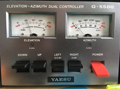
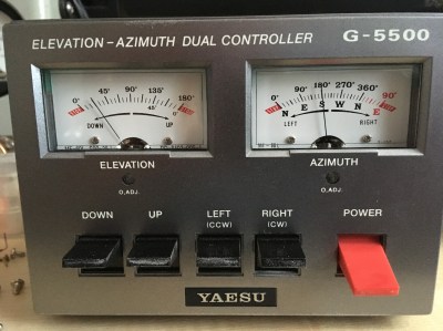
About two weeks ago my Yaesu G-5500 rotator controller developed a strange fault. The Azimuth (AZ) meter would not display correctly, the Elevation (EL) meter was working fine. The AZ meter showed only ~20 degrees but the EME antennas were pointing at 213 degrees. Switching the controller off caused the meter needle to return to 0 degrees, the needle did not appear to be physically stuck.

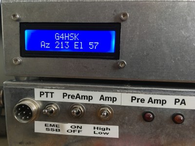
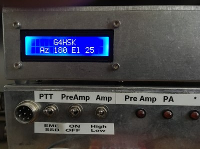
This sort of fault normally points to the rotator itself (most likely internal 500 Ohm potentiometer) or the cabling. I was fairly confident that in my case the problem was within the control box as my K3NG Arduino controller was displaying the correct readings for both AZ and EL. It works in parallel using the same control voltages.


A quick Tweet about the fault resulted in a number of useful paths to follow to try and fix the problem. Close examination of the circuit diagram showed that the AZ and EL circuits were basically identical so I was fairly confident that troubleshooting would be straightforward. I suspected that the problem would most likely be a dry solder joint.

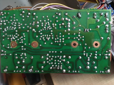
With the control box opened up, it was fairly easy to check voltages at various points and with everything switched off and the circuit board unscrewed from the meters, check for any obvious solder dry-joints. Everything looked fine, clearly without remaking each soldered joint I couldn’t be 100% certain but certainly none looked dull or had an obvious matt finish. I reattached the circuit board to the meters, switched on, and both meters read correctly! I switched the control box off and back on again a couple of times and we were back to the ~20 degree reading… clearly something was intermittent.


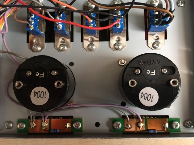
I rechecked the tightness of the meter screws and suddenly the meter was reading correctly. I then removed the four meter screws and cleaned both the meter terminals and the surface of the circuit board where the meter terminals made contact. The board was reattached to the meters and checked. They read correctly first time and have been working correctly since.

In my opinion there should be a star-washer (or similar) between the end of the meter terminal(s) and circuit board to ensure there is a good connection. I didn’t have any available at the time but should the fault occur again I will be certain to fit them. In saying that I can see that it will be a real challenge to do so, which is most likely the reason for their omission at the time of manufacture.

Posted in Blog, EME, Satellites | Leave a comment

10GHz – Frequency Accuracy and Stability

One of the key things that I have learnt from my EME activities is that frequency accuracy and stability is very important. My current 10GHz equipment comprises of a DB6NT G4 Transverter (TVTR) and an ICOM IC-706 transceiver for the 144MHz IF. The TVTR is designed to be used with a (10MHz) reference source. The IC-706 in its standard form does not have this capability, nevertheless it is possible to do, and without any major changes to the radio.

My IC-706 is the early model, what I would call the Mk1. It’s the one that has no push-button band change switches on the front-panel and no 70cms band. It does however have the same reference oscillator (RO) frequency (30MHz) as the later models which is important. Searching the Internet for information relating to “IC-706 Reference-Locking” resulted in very little that was specific to the original Mk1 model however the information by SM6FHZ looked very promising.

Based on my experience of this early IC-706 I would say that the frequency stability is surprisingly good for what is now a rather old radio. After the first 15-30 minute warm-up period the frequency drift on 144MHz was perfectly acceptable for “normal” digi-mode use, with the exception maybe of WSPR. I’ve never run the IC-706 at more than ~10W on digi-modes so it’s possible that at higher power levels the cooling fan may have some effect on frequency stability.

The results above demonstrate that the early model IC-706 is surprisingly stable and is probably fine for use in most radio shacks. However, working portable (/P) where temperatures can vary considerably, and where you may not have the luxury or desire to wait for the equipment to warm up, you need it to be as accurate and stable as quickly as possible. To achieve this an accurate frequency source for both 10 MHz and 30MHz is needed and one that would work outdoors (battery operation) and preferably be GPS controlled. I already have a homemade 10MHz GPSDO but this cannot work outdoors and it is an integral part of the shack / EME setup. So I now had a good reason to purchase the Leo Bodnar GPSDO   🙂

The GPSDO unit arrived within 48 hours of ordering online. It had 2 x 10MHz output as its default configuration. The device was recognised immediately by my Windows 10 PC and the downloaded software displayed the default configuration. I disabled the second output, set the RF output level to minimum and connected the GPSDO to the TVTR. Listening to, and looking at a reference locked 10GHz signal source I could immediately see the frequency correction (<1kHz). The next step was to change the configuration to output both 10MHz and 30MHz. Now this did prove initially to be a bit of a challenge.  Once I had grasped the method of setting the second output frequency I soon had exactly what I wanted. Here are the settings should you need them:

To reference-lock the IC-706 I followed the online information by SM6FHZ

Now, this is written for the later model but having adopted the same approach to my older model I appear to have achieved the same results. There are some minor physical differences to be aware of:

  • The spare hole on the back panel that can be used to accommodate the SMA input connector is different. I used a female to female bulkhead connector with two large washers. Internally a right-angle SMA connector is used with RG-316 cable.
  • The die-cast chassis has fewer cut-outs to facilitate threading the RG-316 cable from the SMA (back-panel) to the RO compartment at the front of the radio. Ideally a thinner (but equally well screened) cable should be used. It’s very tight where the cables go over the central “wall” from the front to rear section of the die-cast chassis.
  • The layout of the RO / filter board and compartment is very different. There is little room to work to add the coupling winding and extreme care is needed not to damage the coil former or winding.

The following photos should help show the approach that I adopted:


Adding the internal RG-316 cabling plus any external cable run to the GPSDO will alter the RO frequency. With the GPSDO and any external cabling removed the RO inductor can be adjusted to compensate for this for times when the rig is used without the GPSDO. With careful adjustment my IC-706 is within +/- 50Hz once warmed up (without GPSDO). This could probably be improved but unlike the later models the RO compartment lid does not have holes to facilitate tuning so removing / replacing the lid affects the frequency. Drilling holes in the lid might affect the temperature / stability… I chose to leave it alone.
With the Leo Bodnar GPSDO set to its lowest power output setting plus an additional 3dB of attenuation things work well. There are no obvious signs of anything untoward when looking at the 144MHz output signal on the spectrum analyser.

Here’s a photo showing the JT65b decodes of the 144MHz beacon GB3VHF. The “DF” is zero and there’s no change. 🙂

Posted in 3cms, Blog, GHz_Bands | Leave a comment

An Arduino Based Antenna Switch For The IC-7300

Since purchasing the IC-7300 I’ve used it mainly on 4m and 6m with the occasional venture down onto the lower bands. With the Sporadic-E season and good conditions on 10m it highlighted one of the shortcomings of the IC-7300… it only has the one antenna socket!

This led me to look at some means of automating this antenna switching rather than having to mess about changing antenna plugs.

The IC-7300 like most other modern transceivers has an output available that tells you which band is in use. This can be either via USB CAT control, the CI-V data interface or a voltage that changes value as you change bands. I initially considered using the CI-V data but decided to use the band voltage.

I wanted something that would:

  1. Be Arduino based.
  2. Switch the antenna path to either my HF antenna, 4m & 6m dual band Yagi, or possibly a transverter.
  3. Switch the RF paths using suitable RF antenna relays.
  4. Have the RF switching part separate from the switching logic.
  5. Provide visual indication of which antenna is “active” and if the transverter is “active”.
  6. If the RF path is switched to the transverter port, provide some safeguard against putting excessive power into the transverter by mistake.

Searching the Internet I came up with a number of commercial and homebrew solutions that automated the antenna switching. So this is certainly nothing new, however the method of construction plus the transverter switching may be of interest. I decided to develop a solution built around an Arduino Nano and one of the readily available four relay switching boards.

The following diagram gives an idea of how the pieces fit together:


Basically the Arduino monitors the band voltage from the rear accessory socket on the IC-7300. A look-up table is used to determine the band in operation. Two RF antenna relays are used to switch to the appropriate output. Any band other than 4m & 6m defaults to the HF antenna path (i.e. no relay is energised). If 4m or 6m operation is detected then Relay 1 is energised and the RF is directed to the dual-band Yagi. If the band is set to 10m an additional check is made to see if the front-panel transverter switch is set to On. If it is, then Relay 2 is energised and the RF path is directed to the transverter via a 10dB pad. A negative voltage (~ -4V to 0V) is also switched to the ALC input on the IC-7300. This voltage is preset and used to ensure that, should the RF output control be set higher, the maximum RF output fed to the transverter does not exceed 1W. If the transverter switch is set to ON and the band is not set to 10m a warning is displayed and the antenna path switched for the appropriate band.

The initial build and proof of concept was done using breadboard and an LCD display. Here are a few shots of the test setup. At this stage nothing was actually connected to the IC-7300, the band change was simulated by adjusting the potentiometer to give a different band-voltage derived from the Arduino 5V supply.


Final construction followed my usual approach, a sheet of Vero (strip-line) board being used to provide the main inter-connections between the Arduino Nano and other various modules etc. The Arduino sketch was modified to allow the LCD to be replaced with an OLED panel.

The IC-7300 band voltage varies between 0-8V. The maximum permitted input voltage on the Arduino is 5V. A simple voltage divider using a small preset potentiometer is used to set the maximum input voltage to 4.95V

I was unable to find on the Internet a set of band voltages for the IC-7300, so once everything was connected I ran through the bands and made a note of each band voltage as displayed on the Antenna Switch display. Once I had these readings a “From” and “To” voltage range was calculated for each band and the look-up table in the program was updated to use these new values. It was interesting to note that the IC-7300 band voltages are not as granular as I had expected, i.e. it does not have a different band voltage for every band. A number of bands share the same values. This can be seen in the table below.

Band voltages – note these measurements are after the voltage divider.

The Arduino and relay board were connected to the Vero Board using 0.1” strip-line sockets and fitted into a Hammond enclosure. The connector on the relay board needed to be extended to enable the boards to slide into the slots that run from the front to back of the enclosure. The unit is powered from the 13.8V supply on the IC-7300 accessory socket. A 250mA fuse protects the IC-7300. A 7805 voltage regulator is used to provide a +5V supply for the Arduino and relay board. The 13.8V is also used to switch the RF relays.

The following photos give an idea of how things fit together:

The in-line 10dB RF attenuator reduces the 10W drive down to 1W which is ideal for my setup. The various tests that I have done to test for ALC overshoot would suggest that the IC-7300 performs very well in this respect, unlike my FT-847. The IC-7300 output power could be reduced further but running at 10W is a compromise between keeping the 10m output as clean as possible and not dissipating a lot of RF (heat) in a big attenuator.

Results:

With the exception of the negative ALC voltage circuit, the original requirements of the antenna switch have all been implemented and it has been in use now for several months. Changing bands (read antennas) is fully automated. To switch the RF path to my 144MHz transverter that’s used for driving the 23cms and soon 3cms transverters the IC-7300 needs switching to 10m, the toggle switch moved to the “on” position and of course the RF output setting on 10m must be set to 10W or less. For me this should not be an issue as I never run more that 10W on the HF / LF bands.  🙂

What’s next:

  1. Implement the negative ALC voltage safeguard.
  2. Run further ALC overshoot tests and document results.
  3. Split the transverter path to allow an SDR to share the 10m receive output.


Posted in Arduino, Blog, IC-7300 | Leave a comment

Revisiting the LDF5-50 MagLoop

I’ve had a lot of fun using the LDF5-50 based MagLoop. By adding and swapping one or more high-voltage doorknob style capacitors it’s been possible to cover the 80m <> 20m bands. The only two negative things being that the loop no longer fits in the back of my new car to go out portable, and as there’s no protection against rain etc. it’s very much a fine weather antenna.

To protect the trombone tuning capacitor a length of large diameter plastic tube was needed and this would have to be cut, shaped, and fitted around the upper part of the antenna. I had a length of suitably sized tubing with end-caps but the tube material was a black polythene plastic type material. I was uncertain about the suitability of this material due to the potential high carbon content. I decided to cut the tube to size and do a set of VNA measurements before and after fitting the cover.

Here are two VNA screen captures before fitting the cover. The loop is tuned to the low end of 80m and the measurements done using the VNArduino analyser.

The second image is with the VNA “zoomed-in” and adjusted for the minimum SWR point.

Here’s a photo with the cover fitted:

Checking again with the VNA showed that the addition of the tube had caused the resonant frequency to change by approximately 10kHz on 80m. This can be seen in the following to screen grabs.

The doorknob capacitors can still be changed by removing the top cap. Two holes allow  screwdriver access to secure the capacitor(s). The trombone can be adjusted by reaching up from the bottom of the tube.

The MagLoop complete with coupling loop.

In hindsight I guess it would have been better to have done the before and after tests with the 20m setup. The next step is to check the tuning for all the bands from 80m <> 20m.
Assuming all is good, it should now be possible to run extended outdoor tests without fear of rain affecting play. 🙂


WARNING:  Because of the very high Q, some capacitors can arc over at power levels as low as 5 watts. Remember also that even with only a few watts of RF power, magnetic loop antennas produce very high voltages across the capacitor(s) and can cause nasty RF burns if touched while transmitting. Care must be taken not to touch the loop when transmitting and to keep a safe distance from the antenna.


Posted in Blog, Magnetic Loops, Mobile / portable Operation, QRSS / WSPR / QRP | Leave a comment

What’s your handle?

For many years I’ve owned a Nissan X-Trail, in fact two, initially a petrol sport and then a diesel. I had an Icom IC-706 with a remote head unit installed. This was used mainly when stationary, with various roof mounted vertical antennas. These ranged from a 40m or 80m mono-band vertical to a tri-band vertical for 6m, 2m and 70cms. The X-Trail had two roof rails that ran the length of the roof. Each had two positions where a roof-rack or bars could be fitted. These were secured using bolts that screwed into the metal brackets that appeared to be welded to the metal roof. This made for a very easy method of fixing an aluminium plate directly to the metal bracket. Any vertical antenna had a robust, well earthed fixing point.

Original bracket used on the X-trail

Last year I changed my vehicle to a Skoda Yeti. I decided that I would not have a permanent radio fitted to this car but still have a mounting point for a vertical antenna that could be used when the vehicle is parked. The obvious solution was to do the same as I had done with the X-Trail. I checked at the time of purchase that the Yeti roof-rails had fixings to secure a roof-rack / bars but I’d not paid attention to the actual profile of the integral roof-rails.

When I came to make a template for the bracket I soon discovered that the surface that this would bolt to was neither horizontal nor vertical! To mount an antenna that was to stand vertical would require some clever metal bending. Given that I was planning to use 1/8th thick aluminium sheet this was not going to be an easy job… at least not with the limited workshop facilities available to me.

Now I’m not one to throw away items that I think may come in handy one day. I’d given up on trying to bend the aluminium sheet. So after much head-scratching and searching in the garage for something that might do the job. I came across an old patio door handle…

There was something about the shape of the extuded aluminium that caught my eye. The angle of the two faces looked just about right… could this be made into a suitable mounting bracket?

I removed the hardwood handle and offered the aluminium bracket up to the Yeti and the angle was just right. So after a few measurements and carefully scribed lines I set to with a hacksaw. I basically cut the handle in half and then cut off the part that the wooden handle attached to.

This left me with the following shaped bracket.


After some further measurements and checks the holes were drilled for the antenna base and the roof-rail mounting bolts. The Yeti roof-rails have “captive-nuts” that are pressed into the alloy rail. These protrude slightly which meant that the new bracket would not fit nice and flush to the rail. To overcome this I made a thin filler plate with over-size holes that would fit between the rail and the new bracket.

The following two photos show the bracket and filler plate after they were spray-painted to match the Yeti roof-rails. Note that some of the metal was masked off so that an earth connection was maintained.


The bracket was fixed using two 6mm stainless-steel bolts and star-washers. The coax runs along the roof gully and down the side of the rear C-pillar all the way down to bumper level where it then enters the boot space through the standard Skoda provided grommet for caravan wiring.

This has resulted in a neat installation that has worked well with the tri-band VHF / UHF vertical antenna and single band 80m and 40m verticals. The 80m and 40m aerials are only attached and used when the vehicle is stationary as I consider them to be too large to be attached to the vehicle when it is moving.


Disclaimer:

This installation does not use the roof-rail fixings as intended by the manufacturer. It’s possible that attaching an antenna in this way could result in damage to the vehicle or  the bracket and antenna breaking away from the vehicle. The size of antenna and whether being mobile or not will certainly impact this risk. Should you decide to adopt any ideas similar to what is described here you need to satisfy yourself that your installation is safe and not contravening any local laws etc.

Posted in Blog, Mobile / portable Operation | Leave a comment

Revisiting the LDF4-50 MagLoop

Today I decided to enjoy the fine weather and do some further outdoor tests with the LDF4-50 MagLoop. I constructed this loop last year. Up until now this loop hasn’t really been used, all my MagLoop experiments have been done using a slightly larger LDF5-50 MagLoop.

I remembered that I had a telescopic pole with a tripod base somewhere in the garage. This was used several years back to support a single 2m yagi for my initial EME tests. With a sufficient length of plastic tubing this would support the MagLoop nicely and be easily transportable.

I set the loop up so that the tuning capacitor was just within my reach, so I guess the top of the loop was just over 2 metres above ground. For these tests I was also using the coupling loop fixed in a slightly different position.

All the measurements were done using my VNArduino network analyser. The MagLoop was connected directly to the analyser with approximately 15 metres of coax, and the same coupling loop / position used on all bands.

Here’s the test bench:

G4HSK Antenna Test Bench

and the MagLoop plus a close-up of the coupling loop:

G4HSK_LDF4-50_MagLoop

G4HSK_LDF4-50_MagLoop_Coupling_Loop

I plan to use the MagLoop out portable, and when at home, tuned to 28MHz for QRSS. It covers 14MHz to 30MHz. The coupling loop seems to work well and I’m pleased with these results.  I think it should work well on 28MHz.

Here are the VNA measurements for each band:

The next step is to waterproof the coupling loop and tuning box.


WARNING:  Because of the very high Q, some capacitors can arc over at power levels as low as 10 watts. Remember also that even with only a few watts of RF power, magnetic loop antennas produce very high voltages across the capacitor(s) and can cause nasty RF burns if touched while transmitting.

Posted in Blog, Magnetic Loops, Mobile / portable Operation, QRSS / WSPR / QRP | Leave a comment

A ProgRock and a very old MMT 144/28 Transverter

Having got the 10MHz side of the ProgRock project working (see here for details) the next stage was to look at the 116MHz output. If this was also acceptable, I would have an alternative means of generating the two frequencies (10MHz & 116MHz) necessary to ensure that my 2m and 23cms transverters were “on frequency”.

As with the 10MHz output the 116MHz output was a square-wave and a simple 7-element LPF (Low Pass Filter) was added. A quick look at the output on the SA (Spectrum Analyser) showed that the 3rd harmonic was ~ 38dB down on the wanted 116MHz output.

The output on an oscilloscope looked like this:

The final stages needed to complete the physical build of the ProgRock project was to build a small voltage regulator board and house everything in a standard “HSK project” die-cast box. The regulator board was needed to allow a 13.8V input and output of 5V for the QLG1 GPS receiver module and ProgRock module.

Once everything was fitted into the die-cast box I could start to use the QLG1 GPS receiver and check the frequency stability without fear of draughts or physical interaction / movement affecting the tests. The initial tests were done using SpectrumLab to view the 10MHz output. It can be seen from the next screen that the output showed no signs of drifting.

I was now at the stage where I could try to use the ProgRock to improve the frequency stability and accuracy of a very old MMT 144/28 2m transverter.

I purchased the Microwave Modules MMT-144/28 2m transverter new, way back in the early 1980s. It was originally used with a Yaesu FT101b and later with the ICOM IC-735.  When I acquired a Yaesu FT-225RD the transverter was “retired”and has basically been sat in a cupboard gathering dust since then. In its day the MMT 144/28 transverter was very popular, many are still in use today.

The local oscillator specification of the MMT 144/28 was quoted in the owner’s manual as being:

In its day that was acceptable for normal SSB and CW operation, but by today’s standards, especially for digital modes, it’s far from acceptable.

So the first test was to see if the transverter still worked, and then to see what the frequency stability and accuracy was like. I applied power to the MMT 144/28 and carefully monitored the current drawn and looked for any escaping magic smoke. It passed this test and seemed quite happy.  Tuning to GB3VHF proved that everything was working but the frequency was off by >1KHz and things were drifting.

A test on transmit, with the transverter running ~ 2W into a dummy load, showed that the transmit signal was drifting about 20Hz over a one minute period.

Clearly this would not work well with any of today’s digital modes. So the next step was then to try to either “reference lock” the original 116MHz oscillator or replace it with the 116MHz output from the ProgRock. For simplicity I chose to do the latter.

Fortunately the MMT 144/28 has a spare BNC socket on the back panel so it was easy to feed in the external 116MHz signal. Levels were adjusted using a 1dB stepped attenuator while monitoring the MMT 144/28 output on a spectrum analyser.

Here are the initial test results:

The 116MHz local oscillator (ProgRock) is ~60dB down and harmonics >55dB down.

Frequency accuracy and stability is vastly improved. The following screen grab shows GB3VHF (in-between keying sequences). The minor “glitches” are the 1PPS corrections taking place in the ProgRock.

The real test was to see if / how this 35+ year old transverter would work with today’s digital modes, in particular JT65b. To do this I used the MMT 144/28 and my TS-2000 (on 28MHz) in place of my normal 2m receive EME setup (K3 + Anglian transverter). The results were very encouraging, as the following screen grabs show:

Now I happen to know that Conrad, PA5Y uses a GPSDO for frequency control so the 8Hz difference between the DF and Dop: values is down to my TS-2000 which is not GPSDO disciplined, and not the ProgRock! 🙂

I continued to decode a number of stations including UR3EE and the Z66EME Dxpedition.

Arguably receiving these stations is hardly surprising given that the MMT 144/28 is being used with a masthead mounted LNA, but the key thing for me is the frequency accuracy and stability. This is especially important when operating EME, especially on the higher bands!

The next steps:

  • To check the MMT 144/28 alignment on both transmit and receive.
  • Run some further long-term tests and measurements on both receive and transmit.
  • Test the MMT 144/28 in conjunction with the SG-Lab 23cms transverter.


Posted in 23cms, Blog, EME, GHz_Bands | Tagged , | Leave a comment

Building a ProgRock kit for use as a frequency reference for VHF / UHF Transverters – 1

The ProgRock is a kit produced by QRP-Labs. It is described as a triple GPS-disciplined programmable crystal, based around a Si5351A Synthesizer. Having read positive reports on the ProgRock I decided to order one, plus the optional GPS kit. I also ordered two LPF (Low Pass Filter) kits. The intention being to build a GPS disciplined 10MHz and 116MHz reference source to be used with a 2m and 23cms transverter.

The construction of each kit was straightforward. I opted to implement the recommended ProgRock power option (4.3.1 in the build instructions). Rather than use the standard supplied 27MHz quartz crystal, I also fitted a 27MHz TCXO module for improved performance.

Here’s a photo of the partly completed setup:

The above shows the ProgRock (top LH corner), two LPF boards (10MHz and 116MHz in the top RH corner) and the largest board being the GPS.

My initial testing was all done without the GPS board connected and focused on the 10MHz output. I was keen to understand how clean the output would be and the phase noise. The latter being possibly beyond my means of measurement.

A Farnell Lab (linear) PSU was used to power the ProgRock and this was set to provide 7V for the initial tests. It was very easy to program the two desired frequencies using an Arduino and the provided Sketch on the QRP-Labs web site. I did a quick test without any filtering in place, and as to be expected the 2nd and 3rd harmonics were very evident, being only approximately 18dB and 15dB down respectively.

The output of the S15351A Synthesizer is square wave, so a LPF on each output helps to reduce the harmonic content and provide a sine wave output. The following photo shows the 10MHz output with the LPF in circuit.

The addition of the LPF certainly reduced the harmonic content, they were now >60dB down but there were still significant spurs lower in frequency, close-in to the wanted 10MHz output. To try to improve things further I built a simple Quartz crystal filter using two 10MHz HC-49US crystals.

Here’s the response of the simple crystal filter:

The addition of a 10MHz Quartz Crystal filter reduced the unwanted spurs by a further 10dB or more. Now the unwanted spurs are very close to being 70dB down. 🙂


The next steps:

  • Check the stability of the 10MHz output with just the TCXO and then to add the GPS control.
  • Look at the 116MHz output and repeat all the measurements / tests.
  • Assuming the results are acceptable, build a small regulator board to allow the complete setup to work from 13.8V and house everything in a standard “HSK project” die-cast box.  🙂


Posted in Blog, EME | Tagged , | 1 Comment

LDF5-50 MagLoop on 80m

When I first made this MagLoop my goal was to be able to use it on the 40m band, and this was achieved. Recently I began to wonder if it might also work on 80m.

So the MagLoop was setup indoors (temporarily) to allow the tests to be done in the warm.  🙂

Fortunately I have a very understanding XYL  🙂


Using a handfull of mica-capacitors and my VnArduino antenna analyser it did not take long to establish how much extra capacitance was needed to get the MagLoop to tune on 80m. With an extra 500pF, in parallel to the 120pF needed for 40m, the VSWR graph looked good. Having established the value needed, the next step was to search the shack spares-box for a suitable high-voltage RF style door-knob capacitor. Fortunately I had just what was needed.

This is the arrangment for 80m:


I knew that the VSWR looked reasonable and I could put RF into the antenna, but would it actually radiate and be heard / seen anywhere?  To test this I used my Ultimate3 MEPT  configured to transmit alternate periods of FSKCW6 and WSPR. The output power was ~200mW into 10 metres of RG-58 connected directly to the MagLoop, no ATU was used.

Given the current band conditions the results were very encouraging. The following photo shows the WSPR spots over a 12 hour period:

80m WSPR results 200mW to indoor MagLoop


Here are some QRSS results. Note that the first photo has been edited and the letters G4HSK added above the FSKCW to help you find my trace:

This slideshow requires JavaScript.


By using various combinations of the three door-knob capacitors (500pF / 120pF / 57pF), in parallel with the trombone-capacitor, the MagLoop can now be used on all bands from 80m through to 20m.


WARNING:  Because of the very high Q, some capacitors can arc over at power levels as low as 5 watts. Remember also that even with only a few watts of RF power, magnetic loop antennas produce very high voltages across the capacitor(s) and can cause nasty RF burns if touched while transmitting. Care must be taken not to touch the loop when transmitting and to keep a safe distance from the antenna.


Posted in Blog, Magnetic Loops, QRSS / WSPR / QRP | Leave a comment

Homemade Satellite Antenna

I was at one time quite active on the early OSCAR satellites. In those days (I’m going back over 35+ years) it was 2m to 10m linear transponder(s). Having not done anything with satellite communications for such a long time I decided it was time to see if I could hear myself via one of the latest CubeSats that uses a 70cms to 2m transponder.

To do this I needed a small 70cms antenna that could be pointed at the satellite. I already have suitable antennas for the 2m down link. Now there are many web-sites that describe how to make a suitable antenna and so I don’t propose to repeat that here, but what may be of interest is how I constructed the driven element (DE).

This yagi antenna was based on the K5OE Handitenna and constructed using 4mm aluminium welding rods and 21.5mm PVCu overflow pipe plus a T-piece. All the original element lengths, build details etc. can be obtained from the amsat-uk web-site.

My implementation of this design makes use of two ”Choc-Block” connectors to attach the coax-cable pigtails to the ends of the DE folded dipole. The brass screw-connector pieces, which were removed from the plastic insulation block, are soldered directly to the coax-cable and then pushed through holes made in the PVCu T-piece. The following photos show the idea.

This slideshow requires JavaScript.

This method of construction allows the coax-cable to run back inside the PVCu tubing. Epoxy type adhesive was used to secure the elements in place.

The finished antenna works well and yes, I have tried with one or two of the current satellites and successfully heard my signals coming back on the down link.  🙂


Posted in 70cms, Blog, Satellites | Leave a comment