
Many of the modern transceivers today support direct USB connectivity to your shack PC. This USB connection typically enables 2-way audio and CAT control allowing more or less full control of the transceiver, including PTT keying.
Where CAT control for PTT keying is not possible (older transceiver / software) or desired, a Serial PTT Interface is normally needed. A quick online search will show various ways of doing this. Many of the old designs will refer to the 9-pin D-style “RS232” serial connector once common on PC and laptop machines. Today we normally use the USB connector – although a hardware 9-pin port can often be added, cheaply and simply, where the PC Motherboard already has the appropriate header fitted. What’s common to both of these serial connections is that the state of the RTS line on the COM Port is used to control switching of the transceiver from receive to transmit (RX<>TX).
Here’s a typical circuit using a 4N25 opto-isolator for PTT keying:

To use the RTS line state via the computer USB port a USB-to-serial port adapter is needed. An online search for “USB serial port adapter” will show a vast number of adapters that vary in the chipset used, their size and price / availability. Based on my experience of using various adapters with a Windows OS I have found that FTDI based adapters work well.
I have used the following adapter (SH-U09C) in my recent projects:
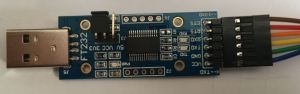
Caution: This adapter requires the RTS status to be inverted. This can be done very easily using the FT_PROG program from FTDI. Once this has been done the adapter simply connects to the 4N25 and it works.
Those of you who are already using this method of PTT keying will know that when you plug the USB adapter in, or boot your PC, the state of the RTS line changes 2 or 3 times which causes erroneous keying of the transceiver. Some people add a switch in the PTT line so that they can stop this happening or they have the discipline to always turn the transceiver on after they have plugged the USB adapter in or after the PC has booted.
Recently Carolyn, G6WRW posted details on Twitter showing how she had added a PTT circuit to the Pluto SDR that she was using for QO-100 operation. This PTT circuit was using the state of two GPIO pins on the Pluto to control the PTT keying. What was interesting to me about Carolyn’s design was that it prevented erroneous keying (of the PA etc.) when the Pluto boots!
It occurred to me that the same approach could probably be used for the USB-to-serial adapter PTT keying. When a PC boots or the USB device is plugged in both the RTS and DTR lines change state several times, so in the same way that Carolyn’s design uses the GPIO state to stop the erroneous keying I could probably do the same but using the RTS and DTR lines.

Fortunately the FTDI USB-to-Serial adapter that I use has the DTR line available on an unpopulated hole on the PCB. As the CTS line is not used I very carefully cut the existing connector pin, removed the remaining piece from the PCB and soldered a link from the DTR connection to the original CTS connector pin. See photos below:

The small square pad of black insulation is there to ensure that the DTR line (red wire link) does not short to the CTS solder pad should the connector flex when connecting the ribbon cable.
The three connections (DTR, RTS and GND) from the FTDI USB-to-Serial adapter connect to the circuit above and the PTT connections go to the transceiver or sequencer etc.
Observations:
This method of using both the RTS and DTR lines has stopped all the erroneous keying that used to occur.
Many different Digi-Mode programs have been tried (WSJT, WSJT-X, MSHV, Fldigi etc.) and they all work as expected with one exception. I discovered that if the USB-to-Serial adapter is unplugged then plugged back-in and WSJT is started, when the operator commands the program to TX, both the RTS and DTR lines go High. As this is the condition where (with the new switching circuit) the PTT line should not be switched, the transceiver does not go to TX. This does not occur if WSJT-X or MSHV is used, with those programs only the RTS line goes High. Interestingly if WSJT-X is run, closed down and then WSJT is restarted, it works as expected and the transceiver goes to TX when commanded. I have experienced this on two different computers with versions 7, 9 and 10 of WSJT.
Based on my experience so far, I believe the benefits far outweigh this slight issue observed with WSJT. Clearly YMMV. If you use any software that does not manage the DTR line status correctly, i.e. perhaps both RTS and DTR are set to go high by design, putting a switch in the DTR line would overcome this issue on the occasions when these programs need to be run.
Acknowledgements:
- Thanks to Carolyn, G6WRW for sharing her design for the Pluto GPIO PTT switching.
