
Having had great success with a loop made using LDF4-50 Heliax and the much smaller 24″ diameter bicycle wheel rim loop I decided to try making a larger loop that would work on the 17m, 20m and 30m bands and also ideally on 40m.
The 40m band was the real challenge given the size of the loop (115cms diameter), ideally the diameter needed to be larger but any bigger and I would not be able to transport it in the back of my car and use it for /P operation away from home.
Construction:
Fortunately I had an off-cut (!) of LDF5-50 available plus some odd lengths of standard 22mm and 15mm copper tube. These items plus some other standard home plumbing bits and pieces would form the loop and a trombone-style tuning capacitor.
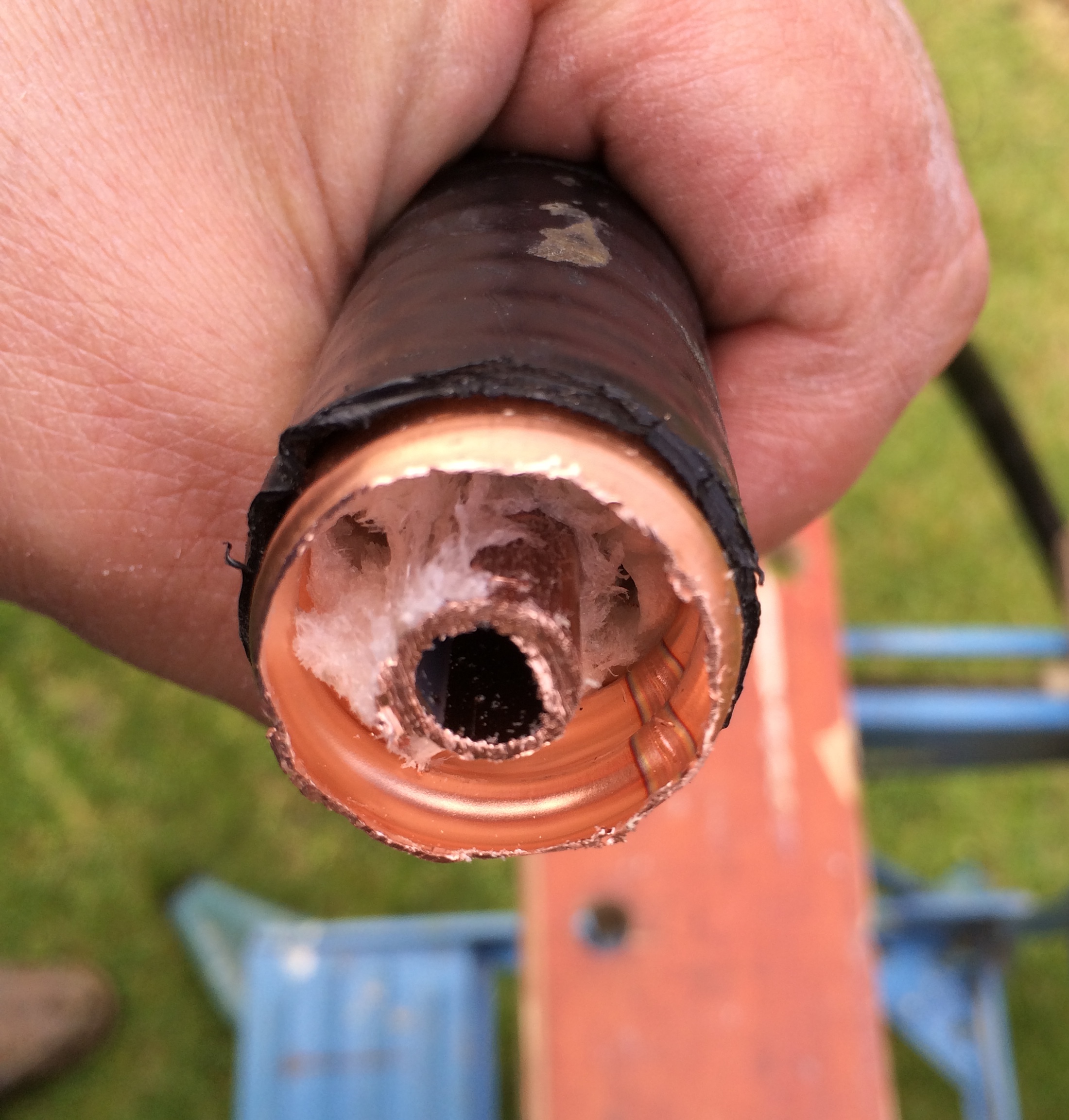
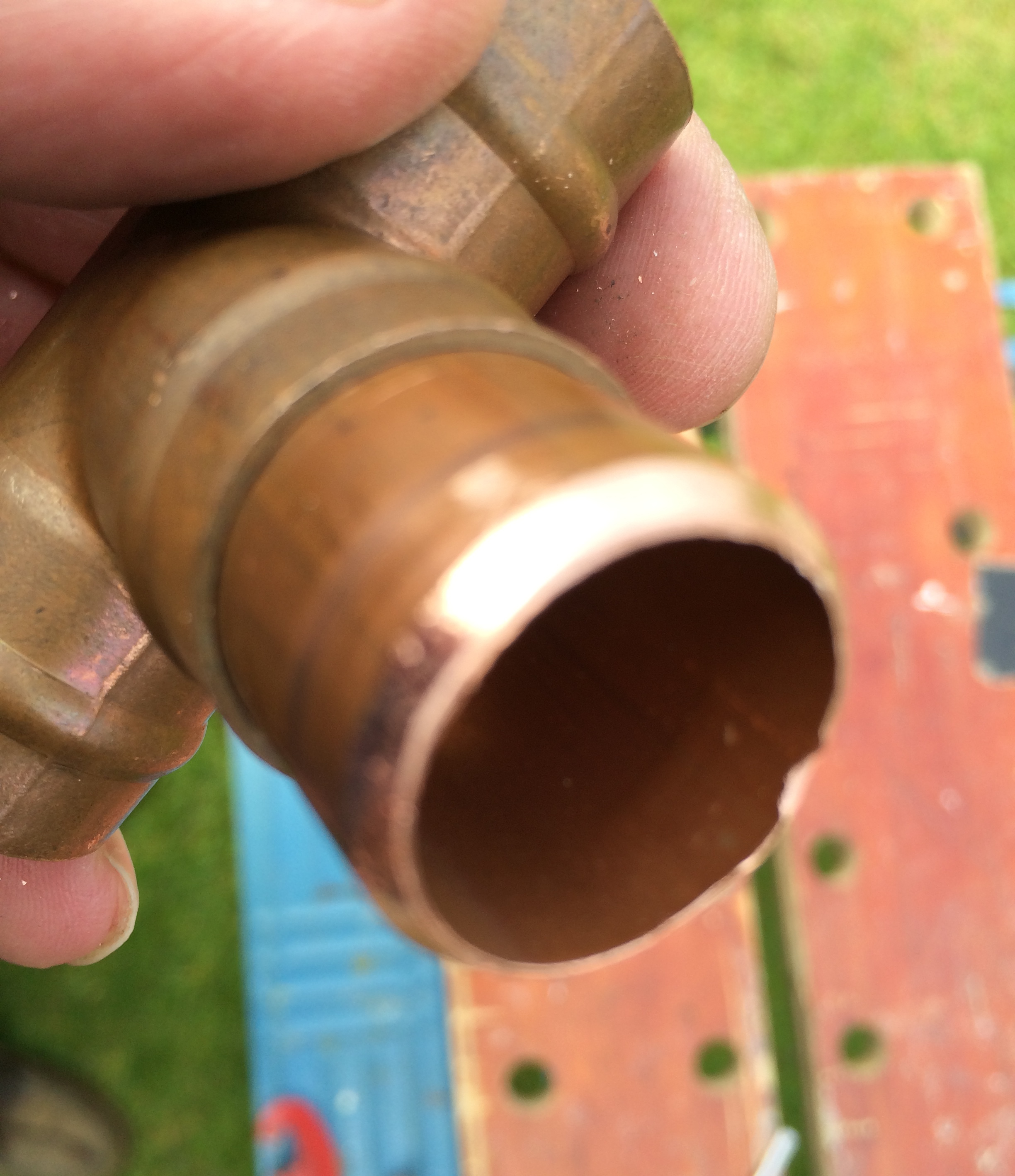
One of the key things with magnetic loop construction is to ensure that you have the minimum number of joints, and where they are necessary, they need to be good both physically and electrically. My first challenge was how to join the ends of the LDF5-50 to the 22mm tubing that was going to form part of the capacitor. I found that with some effort, and great care not to suffer any injury, it was possible to fit a short length of 22mm diameter copper tube inside the corrugated copper conductor of the LDF5-50. This meant that a standard copper T piece could then be used to attach the end of the loop to the 22mm tube that would be used to form the tuning capacitor.
The following photos show the end of the LDF5-50 with the foam insulation removed / compressed sufficiently to accommodate a short length of 22mm tube and finally how the T piece would attach.

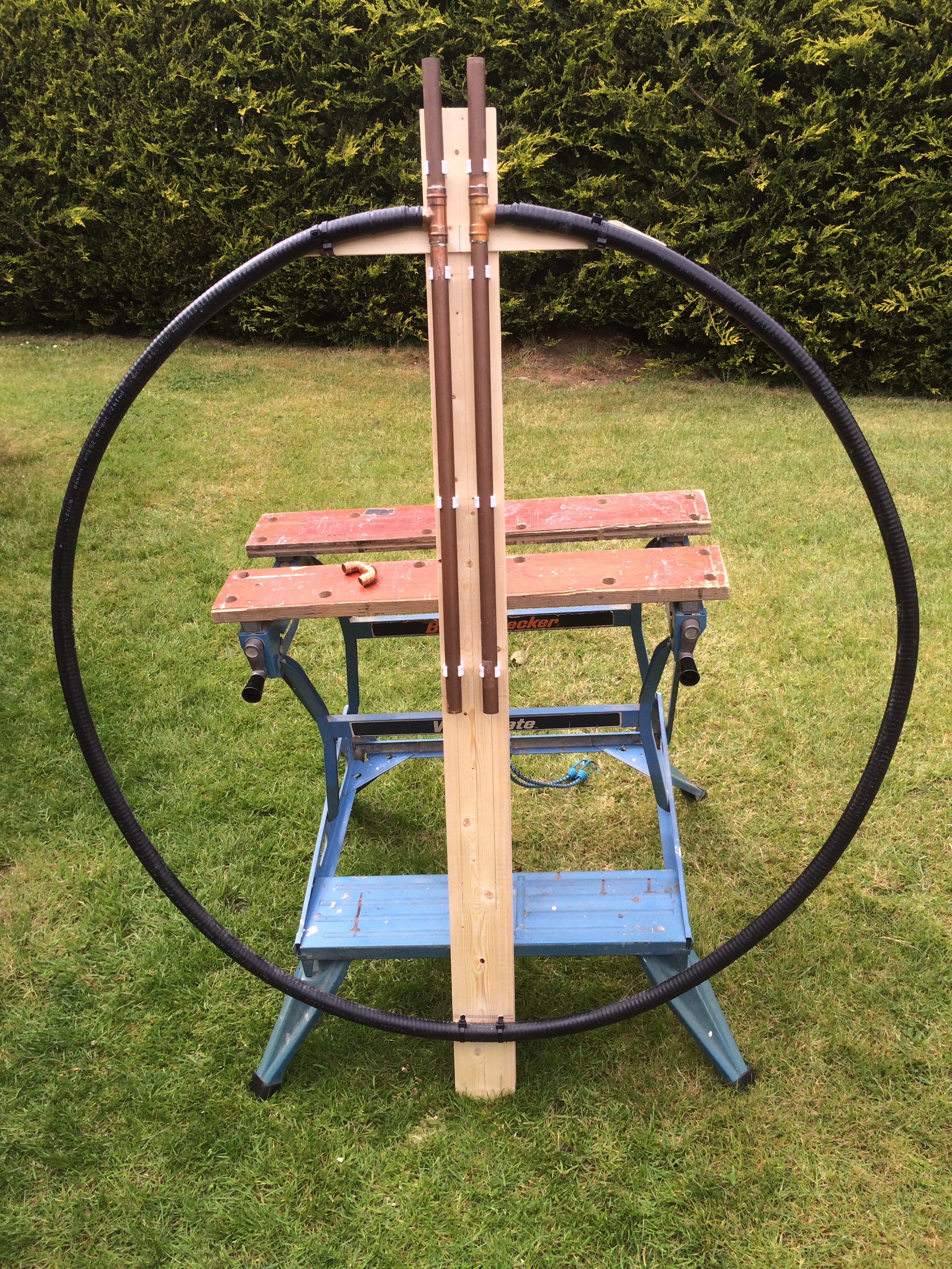
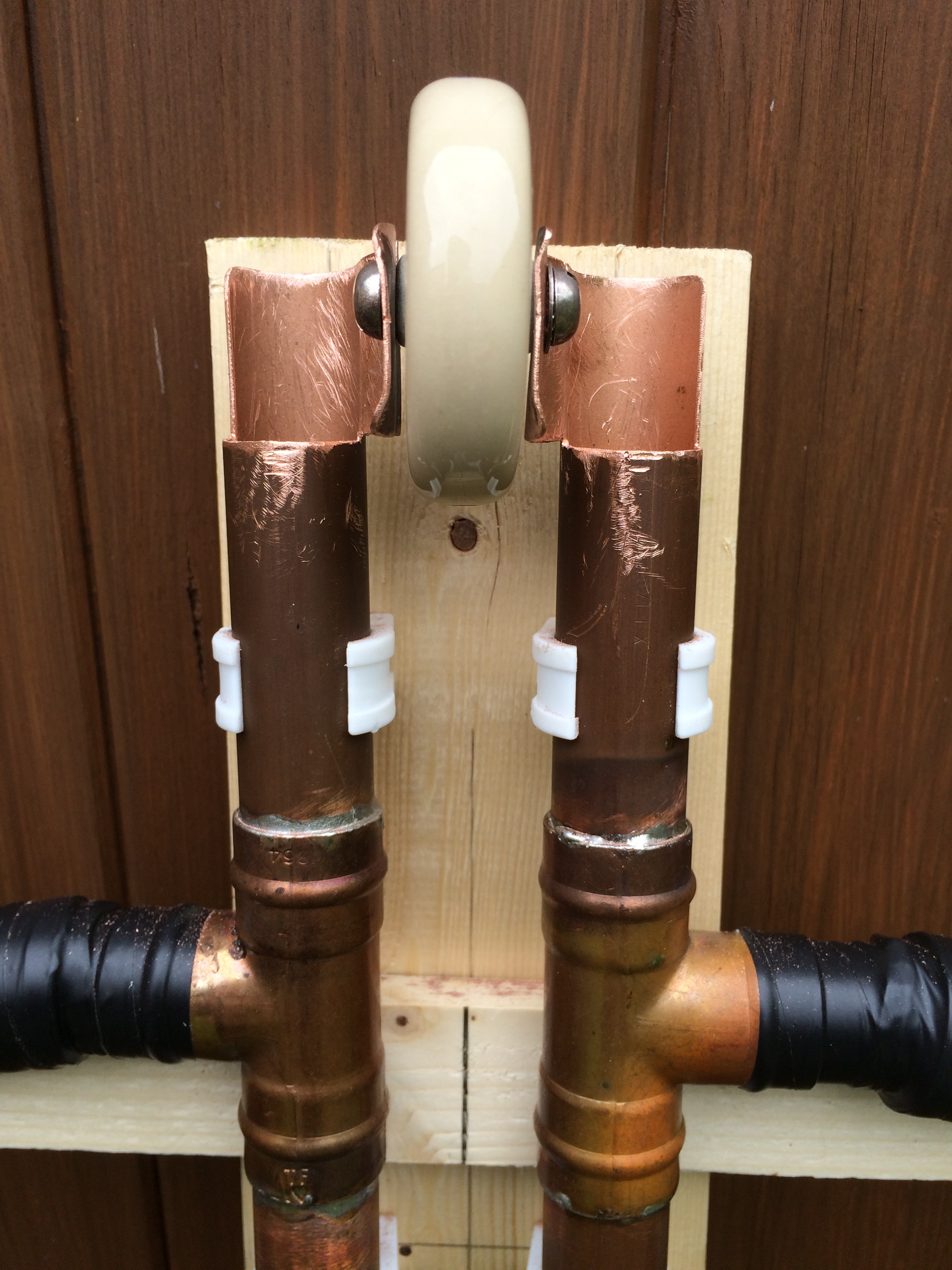
To form the trombone capacitor I cut 4 lengths of 22mm copper tube, 2 were 175mm long, they were to be the upward pointing tubes and the other 2 were 650mm long. In an ideal world I would have calculated the theoretical capacitance of such a trombone arrangement but as in most of my loop projects this was going to be another “suck it and see” experiment. I cleaned up the ends of the copper tube and using an old piece of wood and some metal pipe clamps to hold things in place I carefully shaped the loop so that the ends aligned with the centre of the T-pieces and the two sections of the trombone were spaced correctly and parrallel. Once I was happy with the alignment, using a home DIY plumbing gas torch I soldered the pieces together. When things had cooled I checked that the solder had flowed and all the joints were sound. The ends of the Heliax were then covered with some self-amalgamating tape followed by insulating tape. Then the loop was fixed to a new wooden support using plastic pipe clamps and cable-ties as shown below.
The next step was to fit the plastic tube and make the “U-shaped” trombone that would slide inside the the two parallel tubes. The insulating material was 20mm diameter plastic water pipe. This formed a nice tight fit inside the 22mm copper tube. The internal diameter was approximately 17mm which meant that the 15mm copper tube was a very loose fit.
After some head-scratching and searching of my plumbing spares box I realised that with care the ends of an in-line 15mm solder-ring joint could be used to form a sleeve on the outer end of the plastic tube and with a 15mm olive glued on the end of the 15mm trombone tube it would make for a nice tight action with the tubes running nice and parallel. The following photo shows the end of the 15mm solder-ring fitting that was carefully cut just at the inside edge of the solder ring; epoxy glue was used to stick it to the plastic tube.

I was now at the point where the main loop was complete, all that was needed now was the coupling loop and some basic receive tests could be done.
The coupling loop was made from Westflex 103 coax with the centre, foil and braid all soldered together at each end and formed into a loop that was 1/5th of the diameter of the main loop. A simple 1:1 homemade balun was used to feed the coupling loop.
The initial tests confirmed that the loop would tune 17m and 20m but my goal of 40m was a long way off. It was evident that I needed a lot more capacitance if the loop was to tune on 40m. I couldn’t extend the trombone any more, in fact it was questionable as to whether the already “long” tubes extending inside the main loop might have some adverse effect on the whole setup. I remembered that I had some high-voltage RF type capacitors in my junk box that could possibly help here. Searching on the Internet I found an extremely useful site that had an on-line Magnetic Loop calculator, something I had not come across before when I constructed my previous loops. Entering the dimensions of my new loop and the intended operating frequency and power levels I soon had some very interesting data to consider including the capacitance needed to tune the loop.
Here are the calculated results for 40, 20 and 17m (running 10W).

Loop Calculations (http://www.66pacific.com/calculators/small_tx_loop_calc.aspx)
I decided that I needed to shorten the trombone and in some way be able to add additional capacitance if needed. After some work with a hack-saw, pliers, file and drill the following arrangement was formed.
The slot allows for a 120Pf 5KV working disc capacitor to be fixed in place to allow operation on 40m. Changing this to a similar 57Pf capacitor allows operation on 30m and without a fixed capacitor the loop will tune on 20m and 17m.
40m operation
As my main interest was 40m this write-up will focus on that band. With the 120PF capacitor in-place the trombone would easily tune the loop from 7.000 <> 7.200 MHz. The trombone needed to be moved a distance of 70mm to tune the 200KHz span. With the help of Charlie, M0PZT and his MFJ-259 antenna analyser I was able to very quickly optimise the position of the coupling loop and mark-up a length of masking tape to give a reasonably accurate tuning scale.
The following photos show details of the tuning scale, coupling loop and MFJ readings.


The online loop calculator stated that ideally the loop needed to be larger but as I wrote earlier, any bigger and it would not fit in my car, as a result the expected efficiency was calculated to be somewhere in the region of 22%. At this point everything seemed to suggest that the loop should work, the MFJ results looked good, receive was working well but we all know that it’s how well it radiates in practice that counts…
Would this work in practice?
Yes, rather well it would seem. At the time of writing, I have used the loop on two occasions, both on 40m. My first QSO was with the loop in the garden close to the garage wall, a very quick call resulted in a 57 from a station in Norfolk, I was running 10W and he was running 200W to a dipole . The second occasion was with the loop positioned in the clear, running portable with my trusted IC-735 and with power levels of between 50 <> 100W. On a noisy band around 19:00 UTC with lots of European QRM and conditions described as “Meh” by M0PZT, I was able to work into I, HB9, GM and GI. I was able to set the tuning reasonably well “by eye” using the tuning scale, the trombone capacitor was happy with the 100W power level and there was approximately a +/- 4KHz movement in frequency before the SWR exceeded 2:1. So all in all I was very pleased with the initial results.

What’s next?
- To run further tests on 40m and compare the loop with a full-size 40 dipole.
- To test the loop on the other bands (30m, 20m and 17m).
- Weather-proof the fixed capacitor and trombone
- Investigate how to auto-tune the loop.
- Construct another LDF4-50 loop using butterfly-capacitor
WARNING: Because of the very high Q, some capacitors can arc over at power levels as low as 5 watts. Remember also that even with only a few watts of RF power, magnetic loop antennas produce very high voltages across the capacitor(s) and can cause nasty RF burns if touched while transmitting. Care must be taken not to touch the loop when transmitting and to keep a safe distance from the antenna.
