
Since purchasing the IC-7300 I’ve used it mainly on 4m and 6m with the occasional venture down onto the lower bands. With the Sporadic-E season and good conditions on 10m it highlighted one of the shortcomings of the IC-7300… it only has the one antenna socket!
This led me to look at some means of automating this antenna switching rather than having to mess about changing antenna plugs.
The IC-7300 like most other modern transceivers has an output available that tells you which band is in use. This can be either via USB CAT control, the CI-V data interface or a voltage that changes value as you change bands. I initially considered using the CI-V data but decided to use the band voltage.
I wanted something that would:
- Be Arduino based.
- Switch the antenna path to either my HF antenna, 4m & 6m dual band Yagi, or possibly a transverter.
- Switch the RF paths using suitable RF antenna relays.
- Have the RF switching part separate from the switching logic.
- Provide visual indication of which antenna is “active” and if the transverter is “active”.
- If the RF path is switched to the transverter port, provide some safeguard against putting excessive power into the transverter by mistake.
Searching the Internet I came up with a number of commercial and homebrew solutions that automated the antenna switching. So this is certainly nothing new, however the method of construction plus the transverter switching may be of interest. I decided to develop a solution built around an Arduino Nano and one of the readily available four relay switching boards.
The following diagram gives an idea of how the pieces fit together:
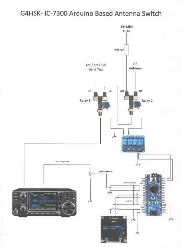
Basically the Arduino monitors the band voltage from the rear accessory socket on the IC-7300. A look-up table is used to determine the band in operation. Two RF antenna relays are used to switch to the appropriate output. Any band other than 4m & 6m defaults to the HF antenna path (i.e. no relay is energised). If 4m or 6m operation is detected then Relay 1 is energised and the RF is directed to the dual-band Yagi. If the band is set to 10m an additional check is made to see if the front-panel transverter switch is set to On. If it is, then Relay 2 is energised and the RF path is directed to the transverter via a 10dB pad. A negative voltage (~ -4V to 0V) is also switched to the ALC input on the IC-7300. This voltage is preset and used to ensure that, should the RF output control be set higher, the maximum RF output fed to the transverter does not exceed 1W. If the transverter switch is set to ON and the band is not set to 10m a warning is displayed and the antenna path switched for the appropriate band.
The initial build and proof of concept was done using breadboard and an LCD display. Here are a few shots of the test setup. At this stage nothing was actually connected to the IC-7300, the band change was simulated by adjusting the potentiometer to give a different band-voltage derived from the Arduino 5V supply.


Final construction followed my usual approach, a sheet of Vero (strip-line) board being used to provide the main inter-connections between the Arduino Nano and other various modules etc. The Arduino sketch was modified to allow the LCD to be replaced with an OLED panel.
The IC-7300 band voltage varies between 0-8V. The maximum permitted input voltage on the Arduino is 5V. A simple voltage divider using a small preset potentiometer is used to set the maximum input voltage to 4.95V
I was unable to find on the Internet a set of band voltages for the IC-7300, so once everything was connected I ran through the bands and made a note of each band voltage as displayed on the Antenna Switch display. Once I had these readings a “From” and “To” voltage range was calculated for each band and the look-up table in the program was updated to use these new values. It was interesting to note that the IC-7300 band voltages are not as granular as I had expected, i.e. it does not have a different band voltage for every band. A number of bands share the same values. This can be seen in the table below.
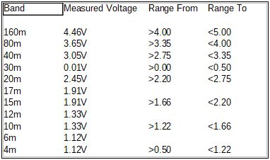
Band voltages – note these measurements are after the voltage divider.
The Arduino and relay board were connected to the Vero Board using 0.1” strip-line sockets and fitted into a Hammond enclosure. The connector on the relay board needed to be extended to enable the boards to slide into the slots that run from the front to back of the enclosure. The unit is powered from the 13.8V supply on the IC-7300 accessory socket. A 250mA fuse protects the IC-7300. A 7805 voltage regulator is used to provide a +5V supply for the Arduino and relay board. The 13.8V is also used to switch the RF relays.
The following photos give an idea of how things fit together:


The in-line 10dB RF attenuator reduces the 10W drive down to 1W which is ideal for my setup. The various tests that I have done to test for ALC overshoot would suggest that the IC-7300 performs very well in this respect, unlike my FT-847. The IC-7300 output power could be reduced further but running at 10W is a compromise between keeping the 10m output as clean as possible and not dissipating a lot of RF (heat) in a big attenuator.
Results:
With the exception of the negative ALC voltage circuit, the original requirements of the antenna switch have all been implemented and it has been in use now for several months. Changing bands (read antennas) is fully automated. To switch the RF path to my 144MHz transverter that’s used for driving the 23cms and soon 3cms transverters the IC-7300 needs switching to 10m, the toggle switch moved to the “on” position and of course the RF output setting on 10m must be set to 10W or less. For me this should not be an issue as I never run more that 10W on the HF / LF bands. 🙂
What’s next:
- Implement the negative ALC voltage safeguard.
- Run further ALC overshoot tests and document results.
- Split the transverter path to allow an SDR to share the 10m receive output.
