10GHz Beacon and SA Down Converter

This project is the result of wanting:

  • A small easy to handle, self contained, frequency accurate 10GHz test source that ccould be used for such things as dish / RX alignment, used as an RF source in conjunction with a power meter for measuring cable loss, filter alignment etc.
  • A QRP 10GHz beacon with CW ID that could be used for longer distance / term tests.
  • A quick and easy means of using my existing Rigol DSA815TG Spectrum Analyser (that’s limited to 1.5GHz) to do some basic signal / spectrum analysis at 10GHz .

I could already do some of what I wanted by making use of an existing 10GHz TVTR as the RF source and a spare LNB for the down converter but it meant that I had to bring various things back into the shack, that then also needed 144MHz IF, a 10MHz reference and power just to do simple cable measurements! The LNB also needed a Bias-T, 12V power and wasn’t ref-locked. A lot of messing about…

The solution was to combine some of the modules that I had used in previous projects to produce a self-contained unit that needed just 12V power.

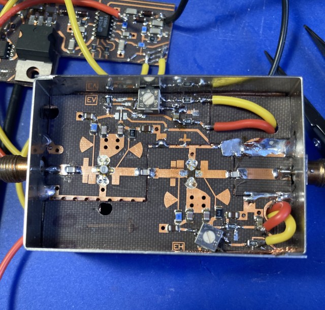
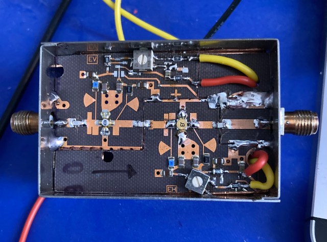
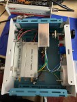
The photo below shows all the modules in place (taken prior to adding all the inter-connect cables etc.)

The six modules are as follows:

10MHz OCXO Module

This low cost 10MHz OCXO forms the heart of this project. Once checked and adjusted for exactly 10MHz output they prove to work very well. The one used here did require a slight modification to get it exactly on frequency. More information can be found online by doing a simple search for “10MHz OCXO frequency standard”. One 10MHz port is used to ref-lock the “ADF4351 SynthShield” module, the second 10MHz port is used by the “10MHz to 25MHz source” module.

ADF4351 SynthShield” Module

For this application it is configured to produce output at either (a) 3456.020MHz or (b) 3456.240MHz. The Arduino sketch will provide either a continuous RF carrier with a 2 second break every 35 seconds on frequency (a) or on frequency (B) a “VVV G4HSK/B  JO01fs” CW beacon Ident followed by a 35 scond carrier repeated approximately every 60 seconds. As a GPS is not being used timings are dependent on the Arduino onboard clock. More detail on this module can be found here.
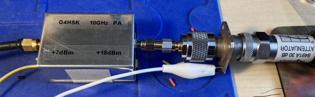
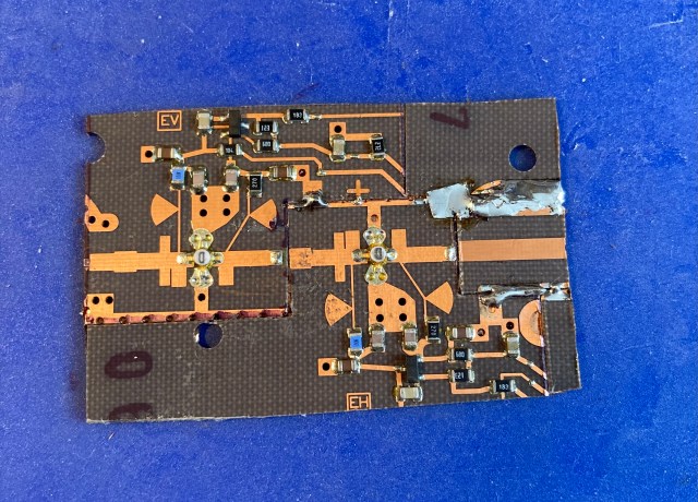
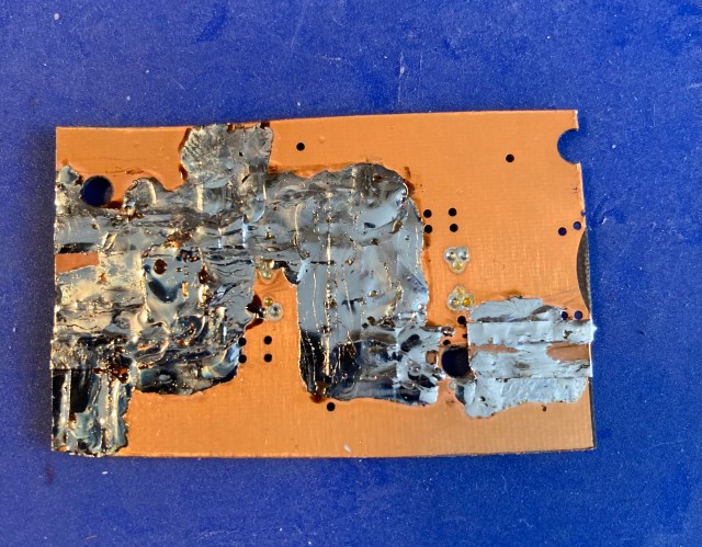
10368MHz LO Module

This module muliplies the 3456MHz output from the ADF4351 SynthShield Module and produces +7dBm output at 10368MHz. This is the second LO board I have built and it has proven that it’s a reproducable signal source for 10GHz. More detail on this module can be found here.

10MHz to 25MHz Source Module

This module filters the 10MHz from the OCXO, divides the filtered 10MHz by 2 using a 74HC390 to produce 5MHz, the 5th harmonic (25MHz ) is then filtered through a 4-pole Xtal ladder filter followed by a MIMIC amplifier stage. The 25MHz output from this module is used to ref-lock the Maclean MCTV-670 LNB module.

Maclean MCTV-670 LNB Module

I have now used this relatively low cost LNB in a number of projects. It’s easily modified to produce a compact module with SMA connections. The ref-locked output from the LNB (618MHz = 10368MHz) is ideal for my Rigol SA and allows me to get some basic idea of whats happening several hundred MHz either side of 10368MHz. More details about modifying the LNB can be found here.

Bias-T Module

This uses a small general purpose “MIMIC / Attenuator / Bias-T board” PCB that I had made and is used to provide 12V power to the LNA via its RF ouput SMA connection.
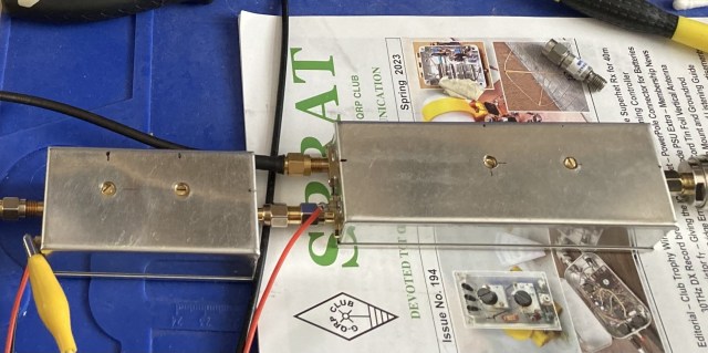
Project Outcome

The beacon / RF signal source works exactly as I had intended. Output is +7dBm which when used with a 6dB attenuator I find to be a nice level for measuring cable loss etc.

The Arduino sketch used on the Arduino / SynthShield is a derivative of the beacon project shared here by IZ1MLT. I modified the original sketch to support either one of two frequencies that can be selected by a jumper / switch on the SynthShield, control a ref-lock LED indicator and to provide either a continuous RF carrier or a beacon with CW-Ident. Once the OCXO has warmed up and settled, the frequency stability and accuracy at 10GHz signal is impressive.

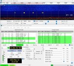
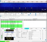
The following photo shows the beacon being received on 10368.720MHz It’s just transitioned from carrier to the start of the CW. The first “V” ( … _  ) of the “VVV G4HSK/B  JO01fs” CW Ident can be seen.

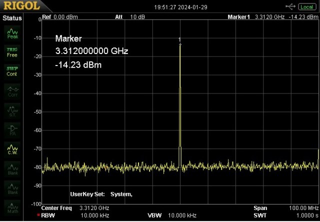
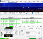
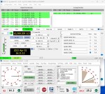
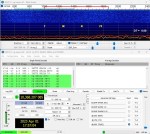
The SA Down Converter works as expected. The screen grab below shows a test signal from the 10GHz beacon on the Rigol DSA815-TG.


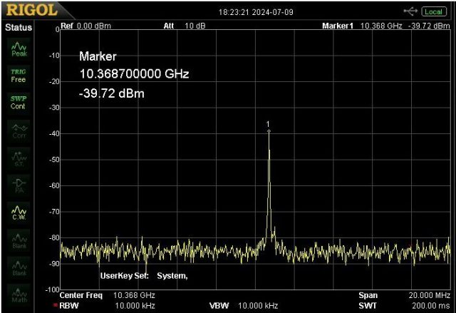
Calibration with a known source is necessary to get some idea of power measurement. However when used for basic spectrum analysis and tuning for maximum gain it works fine. If used with an SDR this module can also serve as a spare 10GHz or QO-100 receiver. Care needs to be taken to attenuate signal levels both on the input to and output from the LNB module. An LNB can have so much gain there is the potential to do damage. I have an attenuator permanently on the output port of the LNB inside the enclosure.

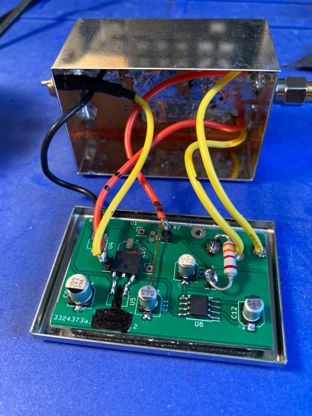
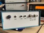
All the above modules were fitted into a Hammond extruded aluminium enclosure. These have now become my favourite type of enclosure for indoor projects. The Aluminium end-plates are easy to work with and the removeable sliding top / bottom panel make for easy assembly. As an added bonus it’s possible to use your favourite PCB manufacture to produce replacement coloured end-panels, all drilled and with silk-screen printed lettering.


Acknowledgements:

  • IZ1MLT for his CW Beacon sketch.


Posted in 3cms, ADF4351, Arduino, Blog, EME, GHz_Bands | Leave a comment

10GHz Transverter Project – Part 5: Finishing Touches

I’ve finally put the finishing touches to my homebrew 10GHz transverter (TVTR) and the lid of the die-cast box was secured for the first time with all six screws!

This project came about for the following reasons:

  • The desire to get out again /P on 10GHz without the need to use any of my existing 10GHz EME setup that I have spent hours and hours optimising.
  • Rather than simply buying another TVTR box “off the shelf”, to see if I could put together a solution using a modular approach based on the lessons learnt getting going on QO-100.

As things stand today the TVTR is working with a 432MHz TX/RX IF plus an optional 618MHz RX output for SDR, about 100mW RF output into WG16 waveguide feed, and all local oscillators are locked to a 10MHz OCXO.

The basic concept did evolve during the build process and end result is as follows:

The TVTR modules have been shoe-horned into a Hammond die-cast box. The internal layout can be seen in the fllowing photo:

The well known “German Tin Boxes” have been used for most of the main modules. To accomodate everything some modules have hade to be stacked two deep.

The main modules being (more details can be found by clicking on the links):

Tests undertaken so far suggest that the TVTR is working well on receive. Both GB3BED and GB3PKT beacons have been audible via RS using just a 20dB horn indoors pointing up through the patio doors.

The rather poor screen shot below shows GB3PKT being decoded at -14dB via RS.

Other than tests done listening to the TVTR on the EME setup and power measurements / spectrum analysis the TX side is still in need of a first QSO.

Lessons Learnt:

  • Based on results so far it would seem that a reasonably good setup can be put together using a mix of “off the shelf”  and homebrew modules.
  • Having built two 10GHz LO boards now, it would seem that the board + “German Tin Box” combination works without any major issues.
  • An LNB plus down-converter can make quite a respectable 10GHz receive setup.
  • My original plan was to use a 144MHz IF but my initial tests showed that the LO leakage was only -37dBc. Changing to a 432MHz IF and with more careful tuning I was able to achieve better than -50dBc.
  • Whilst I’m fairly certain the overal cost (in £££ terms) of this new TVTR worked out less than any one of the few options available new “off the shelf”, it was costly in terms of time and the amount spent on decent internal interconnecting patch leads. Decent SMA connectors and semi-rigid cable do not come cheap.
  • Once the OCXO has stabilised the TVTR draws just over 1A on receive which is higher than I would like when out /P.
  • The commonly available “Chinese 10MHz OCXO” modules work surprisingly well. I did have to make a slight mod to get the pot to “fine tune” correctly but once that was done I was able to zero beat with my trusted G3RUH GPSDO 10MHz source.
  • It’s good to have a PLL Lock LED fitted to indicate things are all “good”. This was one of my finishing touches after I spent time monitoring beacons via RS and unbeknown to me the battery level dropped to a level where the OCXO was not running, the SynthShiel LO was off, and I was listening to white-noise on some obscure frequency!

What’s next:

  • Try to get the TVTR tested using better test gear to get an idea of phase noise, receive sensitivity etc.
  • To try and increase the RF output power from 100mW to around 2W.
  • Make the metalwork to mount the new TVTR, waveguide feed and 95cm offset dish on the new (to me) heavy duty pan and tilt head.
  • To get out more and use the gear /P.
  • Maybe add an SDR panadapter using a RPi and display. This would certainly help when searching for beacons / stations.
  • Find some better local /P sites for testing. Unfortunately Essex has very few high spots!


Posted in 3cms, ADF4351, Arduino, Blog, GHz_Bands, Mobile / portable Operation | Leave a comment

10GHz Transverter Project – Part 4: Driver Amplifier

My goal is to have around 1 to 2W of output power from the 10GHz /P transverter. This power level would be ideal for working Rain Scatter (RS). The basic upconverter produces around 5mW. I’ve yet to find a power amplifier (PA) to do the job at a reasonable price and certainly not one requiring just 5mW input. So the first step needed to be to increase the output to around 100mW.

Fortunately I had a couple of the “Franco” SU-02 10GHz Boards that were part of a recent group buy organised by Phil, G3TCU. These boards appear to have been available for a number of years and as a result there have been many excellent articles describing how to make good use from them.

What I’m showing here is the practical approach and end result of a project based primarily on an article by Geoff, GI0GDP published in an issue of Scatterpoint Newsletter that’s available to all UKuG members.

The SU-02 board looks like this:

It has four devices that can be put to good use. Lots of useful information can be found here

The following series of photos show how the final driver amp patchwork is made up from various sections of the original SU-02 board.

Adhesive copper tape was used on the underside of the board to “knit” all the sections together. It was also tinned to ensure a good ground plane.

Once I had formed the new two-stage board it was trimmed to size to fit in one of the standard “German Tin Boxes”. The red lines in the photo below indicate the shape of each of the patchwork sections.

The various components that were part of the active bias circuit were also removed and two trim-pots added for the new bias arrangement.

Just to prove that my patchwork would still produce some RF output and not let out any “Magic Smoke” I ran some tests with the two original NE32854 devices and the modified bias arrangement. This setup used the PSU section from the “Franco” board.

The following photo shows the original PSU section.

With this configuration I was seeing around 25mW output, things being limited by compression, but it was still amplifying and no smoke!

The next stage was to replace the second device with a MGF1601 and change the bias / PSU arrangement.

With some copper foil carefully positioned to act as a heat shield the NE32854 ws removed using a hot air gun.

Here it is with the pads suitably cleaned up:

The MGF1601 was soldered in place and a new PSU cobbled together using a section of PCB from another project.

With the new driver amp module installed in my transverter I’m currently measuring 75mW output.

The photo below shows the new module installed in the TVTR enclosure.

The top cover of the tin box did cause some instability. Fortunately this was easily resolved by glueing two retangular pieces of RAM to the underside of the cover.

Taking into account the additional loss of the second WG16 to SMA transition (for the power meter) plus various SMA connectors / adapters I suspect that the transverter is putting just under the desired 100mW into the horn / dish feed.

Acknowledgements:

  • Geoff, GI0GDP for his article published in the UKuG Scatterpoint Newsletter.
  • UKuG and others for the detailed information on the “Franco” SU-2 10GHz PCB
  • Phil, G3TCU for undertaking the recent group buy of the SU-2 boards.
Posted in 3cms, Blog, GHz_Bands, Mobile / portable Operation | Leave a comment

10GHz Transverter Project – Part 3: LNB RX Frontend

Modified LNB Transverter Frontend Module

The receive side of my modular /P 10GHz transverter will use a modified LNB as the frontend followed by a down-converter to take the 618MHz output from the LNB down to 432MHz for input to the FT818 (or similar) prime-mover. The Maclean MCTV-670 LNB being my preferred choice for this as I have found it very easy to modify for QO-100 use. See here.

My aim is to have a resonably small compact module with SMA connections for the RF input and output plus the Ref-Lock 25MHz input.

With the PCB removed I took a hacksaw to the Aluminium housing and reshaped it. The following series of photos show what was done.

Original Form

The tubular wave guide section with its Chaparrel Feed Horn was removed. This may possibly be used later on the portable 85cm OS dish.

Round Wave Guide Removed

The F-Type connectors were unscrewed and the protruding sections cut off.

F-Type Sockets Removed and Cut Back Flush With Face

This produced a surface suitable for mounting the replacement SMA sockets. Holes were drilled and tapped to fasten each SMA socket. Two of the original holes needed to be enlarged to accept the long PTFE insulated solder spill of the RF output and 25MHz input sockets. Unfortunately one of the sockets (25MHz) can only be fastened with one  screw but that plus the long length of PTFE insulated solder spill holds things in place without any issues.

The end result is shown below:

This Satellite LNB has the usual arrangement with two probes in the wave guide section, one for vertical polarisation the other for horizontal polarisation. Polarisation switching is controlled by a DC voltage that is applied to the LNB output port(s). Typically 12.0V to 14.5V gives vertical and 15.5V to 18V gives horizontal polarisation. I wanted to keep the TVTR power requirements simple as the intended use was operating outdoors and running off a 12V battery supply. So using the vertical probe as the receiver input meant not having to worry about higher voltages.

Ideally the new SMA input socket would connect via a small coupling capacitor (to ensure DC isolation) directly to the frontend device. To do this would require the remaining part of the waveguide to be removed and some form of mounting block fabricated to mount the SMA socket and allow access to the solder spill. I chose to try a very simple approach and simply reshape the existing probe and solder the end of it to the SMA (via the coupling capacitor) mounted on the original outer wall of the waveguide. A novel approach maybe, but one that needed to be tried.

Modified Input Showing SMA and ATX DC Blocking Capacitor

The above photo shows the reshaped probe soldered to the ATX capacitor / SMA socket. I then added a semi-circular shaped piece of double-sided PCB to close the open end off and covered the top with adhesive backed copper tape.

Modified Input With SMA Socket

I really wasn’t sure just how well this arrangement would work, if at all.  A quick test with it connected to my spectrum analyser showed that it was receiving my shack 10GHz test source without any problem.

We’ve being going through a particular wet spell of weather here recently and it happened to be raining when I finished doing these modifications so the natural thing was to see if I could copy the “local” GB3PKT beacon via RS.

With the LNB connected to a large horn setup indoors pointing out through the patio doors and up at about 25 degrees elevation I could see the GB3PKT beacon on the SDR-Console waterfall. A careful sweep of a ~100 degree arc then revealed a surprise, GB3BED appeared. This was the first time I’d copied this new beacon, it had only become operational earlier in the month.

Neither of the two beacons were particularly strong as there wasn’t really a suitable cell that I could “see” from indoors but I was happy the the modifications seemed to work. The poor quality screen grab above shows both beacons (GB3BED and GB3PKT) on the waterfall. Their true bearings being 304 degrees / distance 77km and 85 degrees / distance 39km respectively from my QTH.

10GHz Feed Horn Used For RS Test

The next test will be to do some Sun noise measurements with a known optimised dish and feed horn setup.


Posted in 3cms, Blog, GHz_Bands | Leave a comment

10GHz Transverter Project – Part 2: TX Up-Converter

Having had success with the Rev2 LO boards the same design changes were applied to the TX Up-Converter board and another order placed on JLCPCB. I prepared the two ½” Pipe Cap filters, drilled the holes in the two side sections of the enclosure and soldered them together ready for the arrival of the new boards. The first board went together quickly and without any issues.

With the LO module connected and the HP432A power meter connected a little (0dBm) 144MHz drive was applied and the filters adjusted for maximum RF out. This was done without the top and bottom covers in place. When I came to fit the bottom cover I detected some output without any 144MHz input!  The cover / metal enclosure was causing some instability. Fortunately this was easily resolved by glueing a retangular piece of RAM to the cover.

The 10368MHz output level was checked while the 144MHz drive level was changed. They both tracked nicely as the stepped attenuator on the IF input was adjusted in 1dB increments. The setup was producing +5dBm output which I was happy with. However on checking the LO leakage (at 10224MHz) it was found to be only -37dBc. This needed to be improved, either by adding additional filtering, changing the IF frequency, or maybe even both.

As the FT-818 covers 432MHz I decided to opt for this as the IF. The ADF4351 + SynthShield was changed to generate the new 3312MHz output. The LO board was then tweaked to work with 3312MHz input and 9936MHz output.

The output from the ADF4351 looked to be okay. The phase noise is still to be checked.

Screen Oscillograph

With this change to a 432MHz IF the LO leakage (at 9936MHz) was measured at -50dBc.

Here the two Up-Converter modules are all boxed up and under test.

What’s Next:

  • Put together the ancillary modules (sequencer, Voltage regulators etc) and try to best guess the layout and size of a suitable enclosure to house everything.
  • Make use of one of the popular “Franco Boards” to create a small 100mW PA.
  • Undertake further measurements and tests to ensure the modules are not producing any “undocumented surprises” 🙂

Acknowledgements:

  • Paul Wade, W1GHZ for sharing his ideas, experience and encouragement to inspire people to have a go and try the GHz bands.


Posted in 3cms, ADF4351, Blog, GHz_Bands | Leave a comment

10GHz Transverter Project – Part 1: 10224MHz LO

Having spent many hours optimising my 10GHz EME setup I decided against trying to use the same gear for /P operation. I had great fun and learnt a lot building my QO-100 up and down converters so I decided I would try and build a second transverter (TVTR) for 10GHz.

I’d read many of Paul, W1GHZ articles where he described how he developed his series of simple low-cost transverters and what he learnt on his way. Encouraged by these articles I outlined my own transverter based around some of the modules I’d built for 2.4GHz / QO-100.

Here’s an outline of my proposed TVTR:

The receive side would use an LNA + modified LNB + my QO-100 down-converter. This would provide a 144MHz or 432MHz IF for the FT-818. This part was already tried, tested and in use on QO-100.

The transmit side was going to be the challenge as I wanted to adopt a modular building-block approach that used the popular “German Tin Boxes” that seem to be used to house many different projects in the world of microwave enthusiasts. It would use an ADF4351 + SynthShield, possibly an old G4DDK004 oscillator multiplier module then a 2556Mhz / 3456MHz multiplier LO module into a 10244MHz + 144MHz mixer / amplifier up-converter module.

The TVTR and LO boards that Paul can supply do not appear to fit any of the standard size tin boxes so I decided that I would try putting my KiCad skills to the test and try to do my own.

After several hours spent working with KiCad I had two PCB layouts that I was happy with. I uploaded a set of Gerber files to JLCPCB and waited for the boards to arrive. Full of confidence I decided to “Go For Gold” opting for the more expensive ENIG finish rather than standard HASL.

JLCPCB did their usual excellent service and the boards soon arrived. They looked excellent as you can see in the following photos:

New Boards and Shiny Tin Boxes

The LO board was assembled and ready for testing. The ADF4351 with its SynthShield providing the 3408MHz input to the LO board, multiplied by three and amplified should hopefully produce around +7 dBm output on 10224MHz (10224 + 144MHz IF = 10368MHz)

Having gained experience constructing pipe-cap filters for 2.4GHz the two needed for the LO board went together without any problems.

Test Fit

Applying volts didn’t cause any Magic Smoke to escape, the current drawn seemed okay but there was lots of RF output on the power meter and that was with a 50R load on the input of the board. It was “hooting” (oscillating) big time and that was without the bottom lid in place! I was aware of the challenges of boxing things up, especially at higher frequencies and I recalled a comment that Paul had made in one of of his articles. I need some RAM (Radiation Absorbent Material) was my first thought. Careful positioning of little pieces of absorber should fix it.

Fortunately I had a small 25mm x 35mm piece of this special and rather expensive material hidden in one of my “safe places”. It was put away probably over 30 + years ago when I started building a G3WDG 10GHz transverter.

I spent much too much time moving small pieces of RAM about in an attempt to stop the “hooting”. Adding some additional Vias was a challenge, trying to do that with wire through 0.8mm thick board is a challenge especially where there’s solder mask present. Extra decoupling also failed to resolve the problem. I went away and read about Microwave PCB Design and in particular guidelines on ground-stitching Vias.

This resulted in a Rev 2 board design and another set of files being uploaded to JLCPCB. With my confidence dented I decided not to go for the ENIG finish this time and just go standard HASL

Five new boards soon arrived, they clearly had lots more Vias compared to my previous boards! Probably so many to make those “in the know” i.e. those with good RF PCB design skills laugh, but my approach this time was “more is better”.  🙂

New Rev2 LO Board

I managed to salvage what I could from the first build. The MIMIC devices, enclosure and SMA sockets were reused. This also saved me some extra metal-bashing which is my least favourite part of any project.

With the new board assembled and soldered into the tin box it was ready for testing. Once again it didn’t produce any Magic Smoke. With just a 50R load on the input this time it did not produce any RF output! Connecting the ADF4351 in a powered off state also resulted in no indication of any hooting. Things were looking up.

With only the two pipe-cap filters to tune the adjustment for maximum output was quite simple. I tuned things first without the bottom lid in place and then with it fitted. The LO module appears to be stable with the lid on or off and without any RAM fitted. Checking the output using the test equipment available to me I could not detect any unwanted oscillations.

With the 3408MHz input from the ADF4351 the LO module produced +6dBm (measured on a HP432A + 18GHz sensor) which is ideal for the mixer input on the TX module.

Using the output of a modified LNB into my Rigol DSA815TG I took a very quick look at the output of the LO. More in depth checks and measurements are planned once the TX mixer board is built and working. For this quick test I did not have the LNB reference-locked to my 25MHz GPSDO source hence the marker not being at 10244.00MHz

10224MHz LO Output


What’s Next:

  • Experiment with an additional MIMIC amplifier btween ADF4351 and LO Board.
  • Compare the 10224MHz output with the ADF4351 running at either 2556MHz or 3408MHz
  • Investigate Ref Locking an old G4DDK004 Oscillator Multiplier board (2556MHz output) and then compare final 10224MHz output (spurs, phase noise etc) against the ADF4351 input at 2556MHz


Acknowledgements:

  • Paul Wade, W1GHZ for sharing his ideas, experience and encouragement to inspire people to have a go and try the GHz bands.


Posted in 3cms, ADF4351, Blog, GHz_Bands | Leave a comment

10GHz Small Dish EME Project – First Initials

This post is just way overdue…

Having spent many hours optimising the dish feed the next step was to see if I could actually keep the dish on the Moon well enough to get my first contact in the log. I tested the TX side by calling CQ unannounced just to make sure that everything switched okay and the PA didn’t get too hot. If it all went pop, only I would know. 🙂

All was good. Next it was waiting for someone with a big dish to come on and then try for my first contact. Moon times were kind, degradation was low but it was a Monday and activity was very low. The following day was looking good, Jan PA0PLY announced that he would be on and looking for contacts to check out the alignment of his dish.

Moon Degradation

Jan was decoding nicely on my side, so via HB9Q Chat we arranged a test. After a few periods Jan sent a -20 report and I replied with R-17. Then I got the RRR and we finished with 73. I had my first 10GHz EME contact in the log.  🙂

I ran some more tests later that week and finished the week off with six Initials in the log. My next period of operation was about a month later. I had been in email contact with Mirek, OK2AQ who was a regular on my WSJT-X waterfall. Mirek was keen to try another test with me. We tried the previous month but unfortunately we failed. We arranged a sked and started off running Q65-60D, I was decoding Mirek but once again I was not decoding at his end so we switched to Q65-120E. It took a while but we eventually completed. Mirek was a consistent -17 with me and he decoded me at -28! My “smallest” QSO partner to date. Mirek has a well optimised 1.8m OS dish setup. Over the next few days I worked a further four new Initials bringing the count to eleven and six DXCC.

Those two operating periods proved that with an optimised small dish setup, it’s possible to complete Q65 contacts with a number of stations and not just the “big-guns”. The AZ rotator continues to be the weak-link in my setup. This will be the focus for 2024.

I’ve not been QRV since last September but am planning to put the gear back on the dish as soon.


Posted in 3cms, Blog, EME, GHz_Bands | Leave a comment

10GHz Small Dish EME Project – Making a W2IMU Feed Horn

Having had good results on receive with my initial setup and established a baseline the next stage was to try and optimise things even more.

I was very fortunate to recently obtain a wave guide (WG) switch so I finally had the missing part to help move from a coax based system to WG16 and reduce the system losses.

I already had an SMA to WG transition and two different feed horns both with WG flanges. The plan was to use these plus my existing Kuhne LNA (MKU LNA 102 A2)  with the new WG switch. When I tried this combination I found that my Kuhne (unconditionally stable) LNA became unstable. Investigation showed that it was unstable if used with anything that had a 22mm round pipe to WG16 transition.

I experimented with different transitions each with a different length taper, tried different overall lengths and different feed horns (Chaparral and G3PHO) on the end of the 22mm pipe. I also tried an expensive well known “off-the-shelf”  SMA to WG transition in place of my homemade ones but I still could not resolve the problem.


Having tested with a known SMA to WG transition the only unknown was the feed horn. With this in mind I decided to make a W2IMU feed horn.

My 1.2m off-set dish has an f/D of 0.61 so the following dimensions were used for the W2IMU horn:

W2IMU Feed Horn Dimensions

The conical section was made from copper sheet, 1.2mm thick. The dimensions for this were calculated using an online tool. To test that I’d got things right I cut and formed the shape out of thick cardboard to ensure that the transition between the two tubes was correct. Once I was happy the shape was cut from copper sheet. This was then annealed (to soften the copper) which then enabled me to hand form the shape around a length of wooden dowel.

Now for the tricky bit… how to align and solder the three parts together without it all falling apart or me suffering any burns. Clearly some form of jig was needed.

Having given it some thought I devised the following based around some threaded studding and a number of appropriately sized discs. The discs were positioned where there was a change in diameter so they aligned and kept each part in place. The top and bottom nuts kept the three circular sections in compression.

The jig worked really well, the three parts were soldered together and once they had cooled the alignment was checked and then the square flange soldered in place.

I had great hopes that with this well proven feed the LNA would be happy. Alas that was not the case, it continued to show signs of instability.  As luck would have it Jan, PA0PLY posted a message to say that a some DU3T WG XLNAs were available. A short time later I had the XLNA fitted to the WG switch and everything was stable.

All the WG parts were shoe-horned in to a plastic waterproof enclosure. A 3D-printed collar and skirt were printed to to go round the feed horn and WG respectively.

3D-printed Feed Horn Collar

3D-printed WG16 Skirt


W2IMU Feed Enclosure On 1.2m Dish


With the W2IMU feed horn position carefully optimised the Sun and Moon noise measurements compare favourably with the VK3UM EMECalc predictions and are certainly better than my previous setup. Moon noise averages 0.5dB.


Posted in 3cms, Blog, EME, GHz_Bands | Leave a comment

10GHz Small Dish EME Project – 1

My experiments with the small 65cms OS dish encouraged me to push on with the work needed to get the 1.2m dish up on the mast. The EchoStar dish had sat in my shed gathering dust for several months. I decided to mount the new dish in the same way as the smaller dish. So a new heavier duty support was needed.

After much measuring, cutting and drilling I ended up with the following:

There is still work to be done. I plan to upgrade the feed support arms with a much stronger bottom support arm to support a new TVTR and PA enclosure. The side support arms will also be spaced further apart at the feed end to allow for different feed systems to be fitted. I hope also to be able to fit the QO-100 feed alongside the 10GHz system.

The new dish did not come with its original LNB and the feed support bracket had clearly undergone some repair with a spot of welding.

Misaligned LNB clamp

I have a laser pointer mounted into a 40mm diameter 3D-printed holder. This was fitted into the original LNB clamp and a few basic feed alignment checks made.

Laser pointer in 3D-printed holder

The laser spot on the surface of the dish was way off the centre-line of the dish and lower than I had expected.

Original repaired LNB holder pointing way off centre-line.

The welded on clamp was removed using an angle-grinder and I refitted the laser-pointer how I expected the LNB to be positioned. This time the laser-spot was on the centre-line and 3.75cms above the physical centre point of the dish surface.

I entered the physical attributes of the dish into one of the off-set dish calculators to get the focal point of the dish. Using a length of cord with knots tied at the three key points I was able to establish that the “front” of my home-brew feed was roughly in the correct place. Not knowing the exact specification of the dish, specifically the designed off-set angle I wasn’t sure where the laser spot should actually “hit” the surface of the dish on the centre vertical axis i.e. should it be 3.75cms above the centre-point? Maybe above or below? I decided the way forward was to fit the feed horn and do some Sun / cold sky (Y) measurements and compare the results with those that EMECalc calculated for my setup.

These initial tests were done using my home-made feed that I’d been using with the 65cms dish. This feed was made from a short length of 22mm copper pipe waveguide with an SMA transition and the Chaparral front section that had been cut off an old LNB. This can be seen below fitted to the smaller dish:

Home made 10GHz Feed Horn

I fitted the feed horn in place and guesstimated where the focal point would be within the Chaparral feed horn, (the centre-line etc had all been checked with the laser pointer) and then fitted the TVTR enclosure below the bottom feed support arm.


TVTR enclosure fitted.

Another unknown at this time was whether the Yaesu G-650C rotator would even allow me to position the dish sufficiently well to get best use of this size dish. The results were good with the 65cms dish but how would it be with a 1.2m dish?

The VK3UM EMECalc program calculated that I should see just over 9dB of Sun noise and 0.3dB Moon noise.


With the noise meter connected to IF output of the TVTR I pointed the dish to where I believed the minimum cold sky noise to be, adjusted the Zero Offset so that the noise meter read zero, and then went for “Gold” and set the K3NG rotator controller to auto-track the Sun.

As the rotator AZ and EL readings approached the heading for the Sun the noise meter needle shot up and back down. My first experience of just how “sharp” this new dish is, and it’s still only 1.2m! What would a 2.4m dish be like??? Now clearly the G-650C is sub-optimal here, a little too fast with a small element of backlash, albeit minimal, and just a simple 500R pot for positioning control but I still believed it could be a lot worse. After all, some of the problems and issues reported on various forums where the so called high-end AZ/EL rotators with HR positioning etc. are not able track accurately etc. do not inspire much confidence and if the question was asked probably most of the owners of these rotators still manually nudge the dish for optimum signal.

I knew that I would have to nudge the dish, and after a few goes with the AZ control buttons I was able to peak the noise level but the Sun noise was only around 6dB… I was so focused on the G-650 and AZ side of things I hadn’t even considered nudging the EL side! A couple of short taps on the rotator controller and the meter was reading 8.5dB of Sun noise. An absolute excellent result. Yes it was slightly down on what was calculated but I put that down to my ability to truly find the expected Cold Sky noise figure. Also nothing had been optimised on the feed side.

The short video below shows how the level of Sun noise changes with short nudges of the dish (the noise meter is set for 10dB full-scale). Note that the EL was not adjusted in the video to peak the noise reading.

The EL side of my setup uses a satellite actuator and this works extremely well. I found that the new dish alignment was different to the original 65cms dish hence the extra nudging required in the early tests. Once I had recalibrated things it tracked very well.

The next test was to see how well I could decode the DL0SHF EME beacon and if I could measure anywhere near the calculated 0.4dB of Moon noise. The rotator was able to “find the Moon” from its park position and track with decodes from the beacon for well over an hour. Were they the best decodes, no not always. The reports varied from -9dB to -14dB, but what was key here for me was the dish was “on the Moon”. With careful nudging I could decode for many periods at -8dB or -9dB which was comparable with others that were active with 1.2m dishes at that time. Oh, and Moon noise? I was able to measure just over 0.3dB so again an excellent result in my eyes.

Manual tracking and decoding of DL0SHF over a 26 minute period.

I repeated these tests over a few days just to ensure that the results were consistent and compared them with two other locals who also have a 1.2m dish setup. The results would seem to suggest that things are working pretty well on receive.

DL0SHF Beacon – G650C auto tracking over 30 minute period.

The above screen grab from Map65 shows the decodes from DL0SHF over a 30 minute period where the G-650C rotator is auto-tracking the Moon. You can see a 4dB variation over that period with -8dB being the best decode. With manual control, and peaking on Moon noise it’s possible to track and keep the beacon close to consistent -9dB as demonstrated in an earlier photo.

Over the last few weeks I have received and decoded 16 Initials (unique stations, including the beacon 🙂 ) via the Moon.


Lessons Learnt:

  • It’s better to get on and use what you’ve got rather than having kit sat on the shelf waiting for that ultimate solution.
  • With care and attention to detail a good small dish EME receiving setup can be put together and give good results.
  • Do not underestimate the head load. The combined weight of the dish, mount, rotators, TVTR +PA and counter-balance weights can really add up.
  • The noise meter is a great instrument to have especially if you need to track manually.
  • Setting the rotator AZ + EL park headings (in PstRotator) so that the dish is pointing at QO-100 satellite is very useful. An SDR tuned to 265.5MHz on the output of my G4 10GHz TVTR  will receive the narrow-band transponder very well. It also a check for correct dish alignment.

What’s next:

  • Upgrade the feed support arms.
  • Try optimising the feed horn position to get a better performance baseline for the full coax setup.
  • Swap over to a WG16 feed setup and redo the optimisation.
  • Experiment with different feed horns.
  • Try PWM speed control on the G-650C motor.
  • Complete the new TVTR + PA enclosure.


Posted in 3cms, Blog, EME, GHz_Bands, QO-100 | Leave a comment

Fun on 10GHz – 5 ‘Completed AD8307 Based Noise Meter – 28MHz / 144MHz IF’

I have been testing the noise meter modules with them connected to the 144MHz IF output of my 10GHz transverter. To make best use of the noise meter when working in the shack it ideally should work at 28MHz, i.e. the IF output of the Anglian 2m transverter. This would then enable me to do measurements on 3 bands, i.e. 144MHz, 1296MHz and 10368MHz. To do this another frontend IF Amplifier module is needed but this time it should be optimised for 28MHz. Fortunately the same PCB could be used, the only changes being the BPF.

I constructed the BPF first and checked the filter characteristics before adding the three MMIC amplifier stages.

Here’s a screen grab showing the BPF characteristics:

28MHz BPF Characteristics

The gain from this new module is currently “only” +60dB as my parts drawer didn’t have three spare MAR-8A+ devices and so had to use slightly lower gain MMICs.

The photo below shows the 28MHz RF Amplifier Frontend board being tested and the meter showing just under 4dB of Sun noise on 10368MHz (using a 65cms OS dish).

The next step was to house the new frontend board in another “German tin plate box” and put all the parts in a suitable enclosure.

This resulted in more melting of solder, drilling and filing…

I also added an internal homemade stepped (1dB to 20dB) attenuator made using small toggle switches and SMT resistors.

My Anglian transverter has a 3dB splitter on the IF output, one side goes to the K3 and the other to a FCDPP for use with Linrad + MAP65 or SDR-Console. The FCDPP unit incorporates an antenna c/o relay and switched 13.5V controlled by the RX/TX sequencer to protect the FCDPP on transmit so I added an additional 3dB splitter to provide the 28MHz IF output to both the FCDPP and the noise meter. The splitter being a simple lumped element Wilkinson divider built on a spare RF relay PCB found in my projects drawer.

28MHz Splitter

I now have a noise meter that can be used outdoors connected directly to the 144MHz output of the dish mounted transverter(s) or used in the shack connected to the 28MHz output of the Anglian 2m transverter with sequenced transmit / receive switching (protection).

The following diagram outlines the various combinations that the noise meter can be used:

Options for using noise meter

The completed noise meter works well. The large meter makes it very easy to see if the dish is pointing accurately at the Moon or Sun. It can be used in the shack in parallel with Spectravue which is still very useful as you can capture and save the results of your measurements / tests.

I’m sure this new piece of test gear will be put to good use setting up and optimising my new dish setup.


Posted in 23cms, 2M, 3cms, Blog, EME, GHz_Bands | Leave a comment