The receive side of my modular /P 10GHz transverter will use a modified LNB as the frontend followed by a down-converter to take the 618MHz output from the LNB down to 432MHz for input to the FT818 (or similar) prime-mover. The Maclean MCTV-670 LNB being my preferred choice for this as I have found it very easy to modify for QO-100 use. See here.
My aim is to have a resonably small compact module with SMA connections for the RF input and output plus the Ref-Lock 25MHz input.
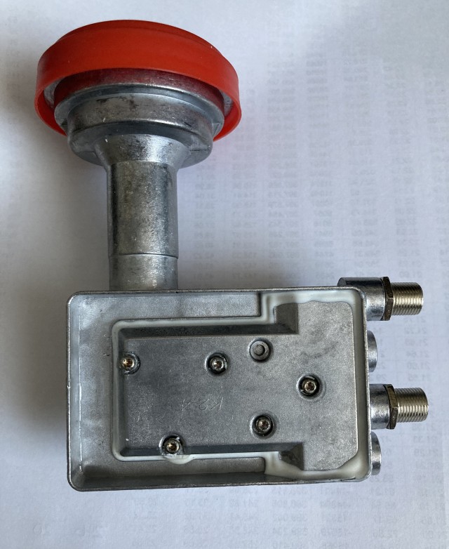
With the PCB removed I took a hacksaw to the Aluminium housing and reshaped it. The following series of photos show what was done.
The tubular wave guide section with its Chaparrel Feed Horn was removed. This may possibly be used later on the portable 85cm OS dish.
The F-Type connectors were unscrewed and the protruding sections cut off.
This produced a surface suitable for mounting the replacement SMA sockets. Holes were drilled and tapped to fasten each SMA socket. Two of the original holes needed to be enlarged to accept the long PTFE insulated solder spill of the RF output and 25MHz input sockets. Unfortunately one of the sockets (25MHz) can only be fastened with one screw but that plus the long length of PTFE insulated solder spill holds things in place without any issues.
The end result is shown below:
This Satellite LNB has the usual arrangement with two probes in the wave guide section, one for vertical polarisation the other for horizontal polarisation. Polarisation switching is controlled by a DC voltage that is applied to the LNB output port(s). Typically 12.0V to 14.5V gives vertical and 15.5V to 18V gives horizontal polarisation. I wanted to keep the TVTR power requirements simple as the intended use was operating outdoors and running off a 12V battery supply. So using the vertical probe as the receiver input meant not having to worry about higher voltages.
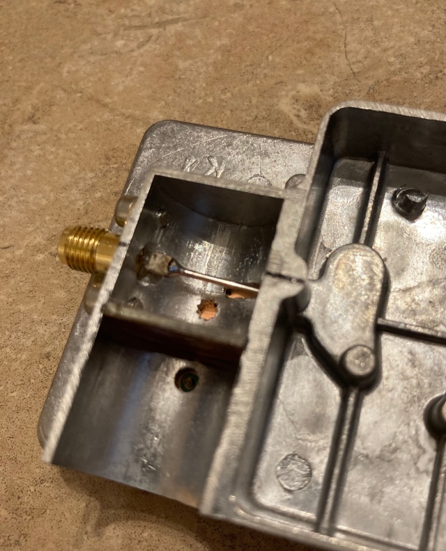
Ideally the new SMA input socket would connect via a small coupling capacitor (to ensure DC isolation) directly to the frontend device. To do this would require the remaining part of the waveguide to be removed and some form of mounting block fabricated to mount the SMA socket and allow access to the solder spill. I chose to try a very simple approach and simply reshape the existing probe and solder the end of it to the SMA (via the coupling capacitor) mounted on the original outer wall of the waveguide. A novel approach maybe, but one that needed to be tried.
The above photo shows the reshaped probe soldered to the ATX capacitor / SMA socket. I then added a semi-circular shaped piece of double-sided PCB to close the open end off and covered the top with adhesive backed copper tape.
I really wasn’t sure just how well this arrangement would work, if at all. A quick test with it connected to my spectrum analyser showed that it was receiving my shack 10GHz test source without any problem.
We’ve being going through a particular wet spell of weather here recently and it happened to be raining when I finished doing these modifications so the natural thing was to see if I could copy the “local” GB3PKT beacon via RS.
With the LNB connected to a large horn setup indoors pointing out through the patio doors and up at about 25 degrees elevation I could see the GB3PKT beacon on the SDR-Console waterfall. A careful sweep of a ~100 degree arc then revealed a surprise, GB3BED appeared. This was the first time I’d copied this new beacon, it had only become operational earlier in the month.
 Neither of the two beacons were particularly strong as there wasn’t really a suitable cell that I could “see” from indoors but I was happy the the modifications seemed to work. The poor quality screen grab above shows both beacons (GB3BED and GB3PKT) on the waterfall. Their true bearings being 304 degrees / distance 77km and 85 degrees / distance 39km respectively from my QTH.
The next test will be to do some Sun noise measurements with a known optimised dish and feed horn setup.


