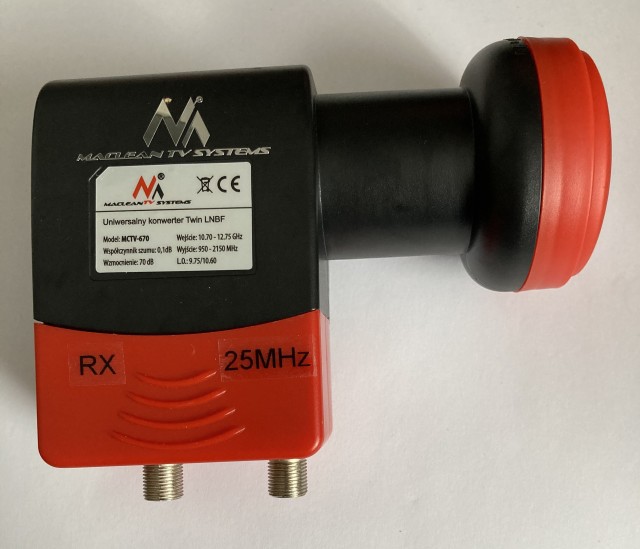
I was asked recently which LNB is most popular with QO-100 users and is the easiest to modify to improve frequency stability. Several “off the shelf” names sprang to mind, they’re often advertised as TCXO controlled or PLL suitable for modification but as far as “most easily modified” I struggled to answer that as it’s dependant on one’s skills, experience, workbench facilities and own perception of what’s easy vs difficult.
I have modified two types of LNB for 25MHz reference-locking. They were single and dual-port devices from Goobay and Octagon respectively. Of the four that I’ve modified one had to be scrapped as I managed to accidentally damage the PCB! Otherwise they all performed as expected after modification.
So what are the typical “hands-on” i.e. practical challenges when trying to reference-lock an LNB with an external frequency source?
- Having the right tools.
- Getting the thing apart.
- Feeding in your frequency reference signal.
- Working with very small Surface Mount components.
- Getting it all back together and ensuring it’s still weatherproof.
Like with most things, there are invariably several different ways to achieve the same end-result, and each way will possibly present different challenges.
I wanted to modify another LNB for use on 10GHz so this led me to look at what people are currently buying and modifying for QO-100 use. My requirements were:
- Two port LNB.
- PLL with standard 25MHz crystal.
- Simple reference-locking while retaining the original crystal.
- “Easy” to modify. 😉
During my online research I came across a section on the QRZ.com page of PA2JSA titled “QO-100: Simple LNB Modification”.
I decided to buy a Maclean MCTV-670 from Amazon UK and it arrived in just under 5 working days.
The plastic casing was easy to remove, first step is to remove the red coloured rectangular shaped part that slides down to protect the F-connectors, then carefully open the two halves of the main LNB body. Do not remove the front red cover.
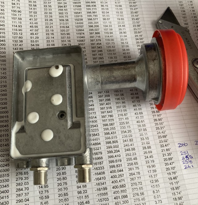
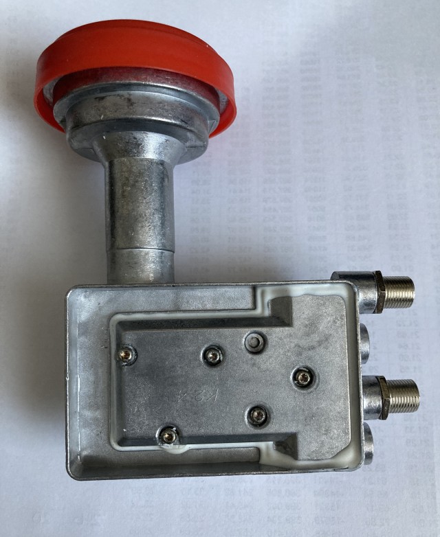
The next step is to remove the white sealant used to waterproof the two sections of the alloy housing. I used a number of wooden cocktail-sticks to do this. Being of softer material and with sharp points they removed all the sealant without any damage to the alloy cover. This then exposed five Torx-headed screws.
I was careful to remove and place all of the screws down in the same position / pattern that they were fitted, just in case one was a different length. I got caught out with a previous LNB that I took apart. Fortunately this time all five screws are the same length.
Once all the screws have been removed the cover needs to be removed. Care needs to taken here as the LNB PCB is only kept in place by a small locating pin and the soldered connections to the two F-connectors. It’s possible that there may be a small amount of sealant between the underside of the cover and the PCB. You do not want to pull the PCB up when removing the cover. I worked from the connector end and used a thin piece of plastic to gently “lift” the cover off.
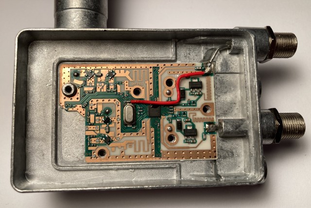
The overall physical design of the LNB is ideal for this modification. The upper most F-connector can easily be disconnected from the PCB and the way the screening walls on the underside of the top cover run it is very easy to route a thin wire from the 25MHz input port to the 25MHz crystal input lead of the RT320M Chip.
I used a 1nF 0805 surface mount capacitor and a short length of PTFE insulated wire to make the connection to the point on the PCB. This is described in detail on PA2JSA’s QRZ page. Soldering the wire to one end of a very small surface mount capacitor does require a very small tipped soldering iron, good lighting and eyesight plus a steady hand. This solder connection is the hardest part of the modification. The photo below shows the completed under the cover modification.
Looking closely you can also see some small dabs of epoxy-glue used to hold the wire and capacitor in place.
Once the modification was done I replaced the cover without any sealant and tested the LNB.
The next two photos show the LNB receiving a GPSDO signal source on 10368MHz in standard PLL form without any external 25MHz locking and then with 25MHz reference-locking. The 25MHz input to the LNB was from my downconverter which has a 10MHz GPSDO input. I found the optimum level of 25MHz input to be around -20dBm.
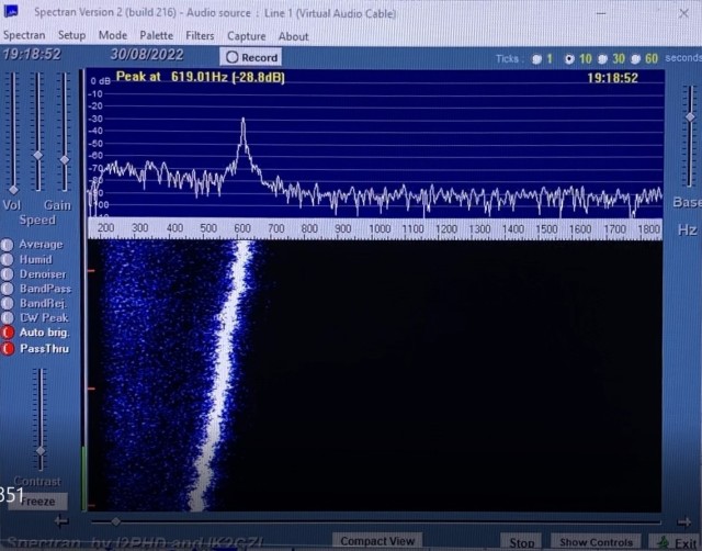
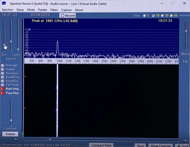 The test results were as expected so the LNB cover was sealed with neutral cure (non-smelling) silicone sealant. The outer plastic casing was then clipped back into place.
Labelling of the two F-connector ports completed the simple modification of the LNB.
Acknowledgements:
- PA2JSA for his QRZ page.
