Given that most modern transceivers today are available with a built-in TCXO module I was sceptical about the need to have a 10MHz GPSDO (GPS Disciplined Oscillator) as part of the equipment in my shack. That was until my interest grew in the GHz bands and various digital modes that are available, particularly working QRSS and Moonbounce (EME).
There are various “off the shelf” GPSDO options available today, some new, some based around ex-commercial units or a mix of both. Or, in true Ham spirit, you can source the individual parts and build your own. A search for “10MHz GPSDO” in your favourite search-engine will reveal many of the options available and their associated costs.
I decided to build my own, to do this I needed a suitable GPS module that had a 10kHz output, a 10MHz OCXO (oven controlled crystal oscillator) with voltage control and a GPS PLL (Phase-Lock Loop) control board. These parts would provide me with a highly accurate 10 MHz frequency standard. This is fine and very useful, but to take full advantage of this standard and to control the accuracy of other pieces of equipment e.g. transceivers, transverters, test equipment etc. multiple 10Mhz outputs are needed. So once the GPSDO was built and working I would need to add an additional distribution amplifier.
Another important requirement when operating digital modes is the accuracy of your PC clock, something I think many operators overlook when I monitor PSK and other modes in use on the HF bands. To ensure accuracy in my own system I had already put together a GPS controlled stratum-1 NTP (Network Time Protocol) server using a Raspberry Pi and an Adafruit Ultimate GPS module. This system used the 1PPS signal from the GPS module. It occurred to me that I could combine both in one unit, so the end result would be a highly accurate time and frequency standard.
So this all developed into a three part project:
- Basic GPSDO with single 10MHz output.
- The addition of a 4 port distribution amplifier.
- To use the 1PPS and Raspberry Pi as an NTP server.
I was very fortunate to have found a new unused Navman TU30 GPS module on eBay; this had the required 10kHz and 1PPS outputs. My first attempt at getting a 10MHz OCXO unfortunately did not work out well, the Morion MV89a had a faulty output capacitor (which I fixed) and a fault with one (or possibly both) oven control circuits… it just kept on cooking. My second purchase, an Isotemp 134-10 OCXO worked out well, the unit was ex-equipment but fully functional. They were the two key parts, and probably the most difficult to source.
There are many different GPS PLL control designs to be found on the Internet. I decided to build the “Simple GPS Stabilised 10MHz Oscillator” published by James Miller, G3RUH and purchased the two printed circuit boards from James. The reason for two boards is that the Isotemp OCXO requires a higher control voltage (0-8V) so a small add-on board with DC amplifier provides a gain of 1.6 x the standard 0-5V provided by the main PLL board.
The following photos show the various parts.
-
-
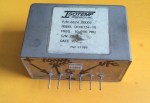
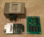
Isotemp OCXO
-
-
OCXO add-on board
-
-
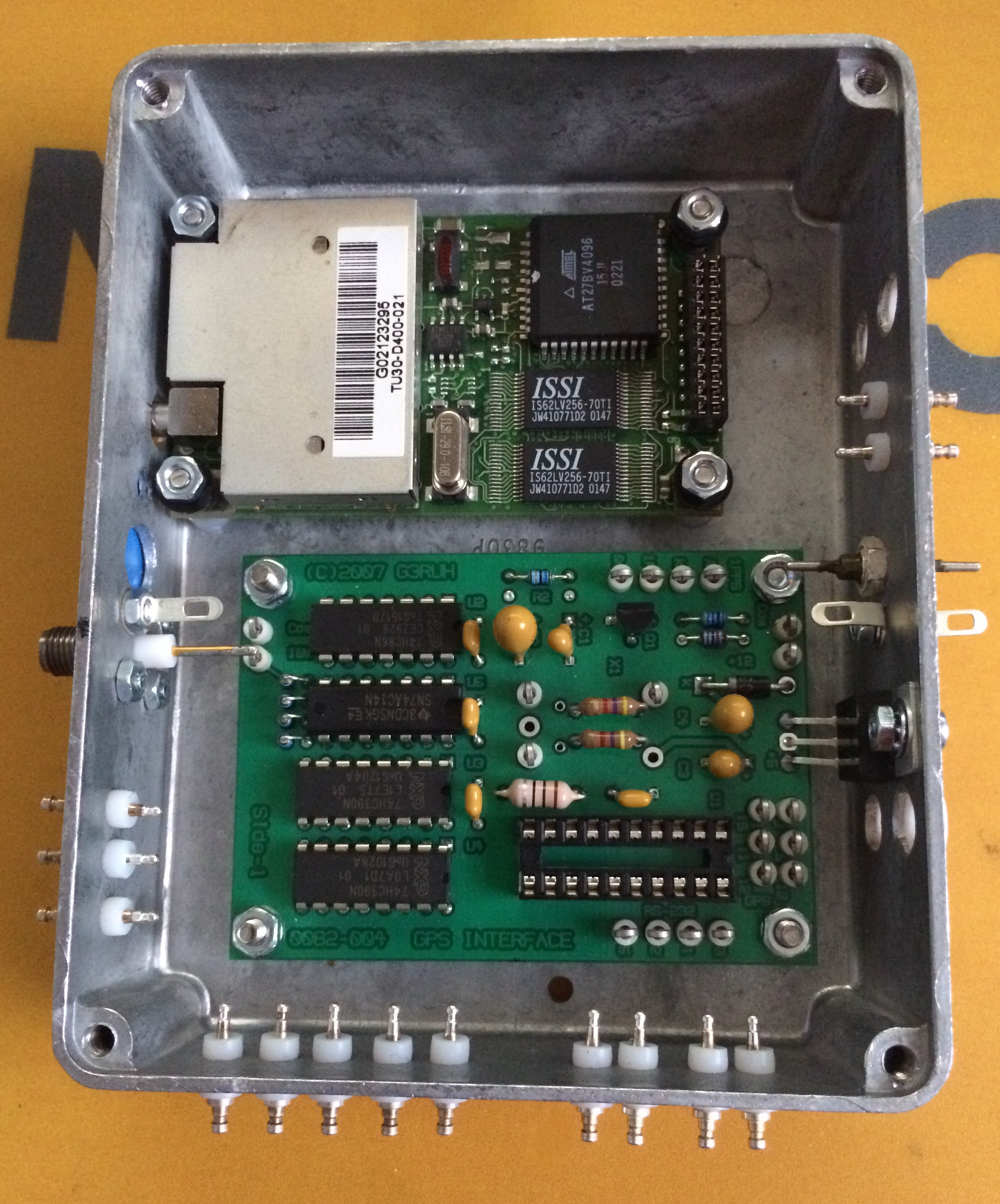
OCXO, GPS and PLL board
Construction and testing:
The completion of the main PLL board and small DC amplifier board was straight forward. If you’re using an Isotemp OCXO and the add-on board it pays to read the documentation for both boards before you start, as a couple of components are not needed on the main board when using both boards… needless to say I had a couple of components to remove!
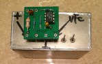
As with most of my projects, I chose to use a diecast box to house the GPS and PLL board.

GPS and PLL board enclosure
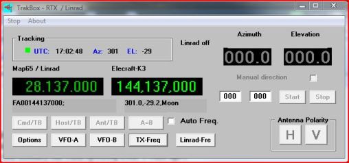
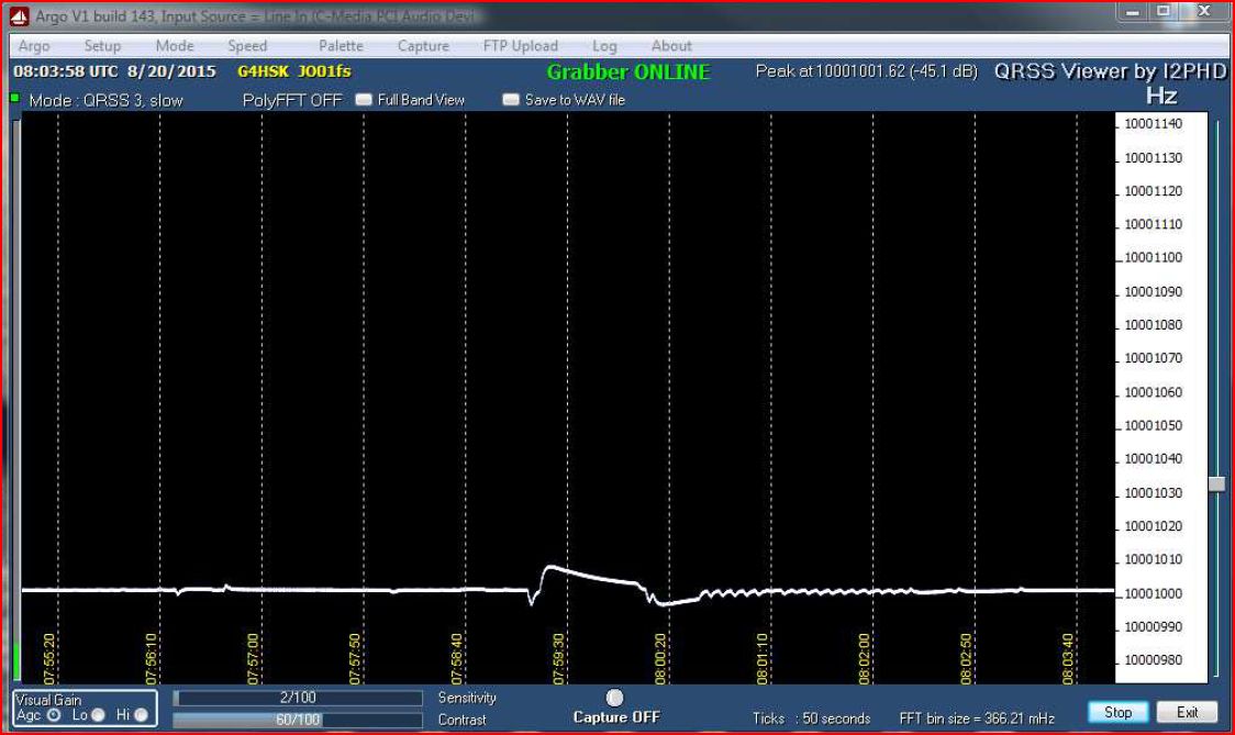
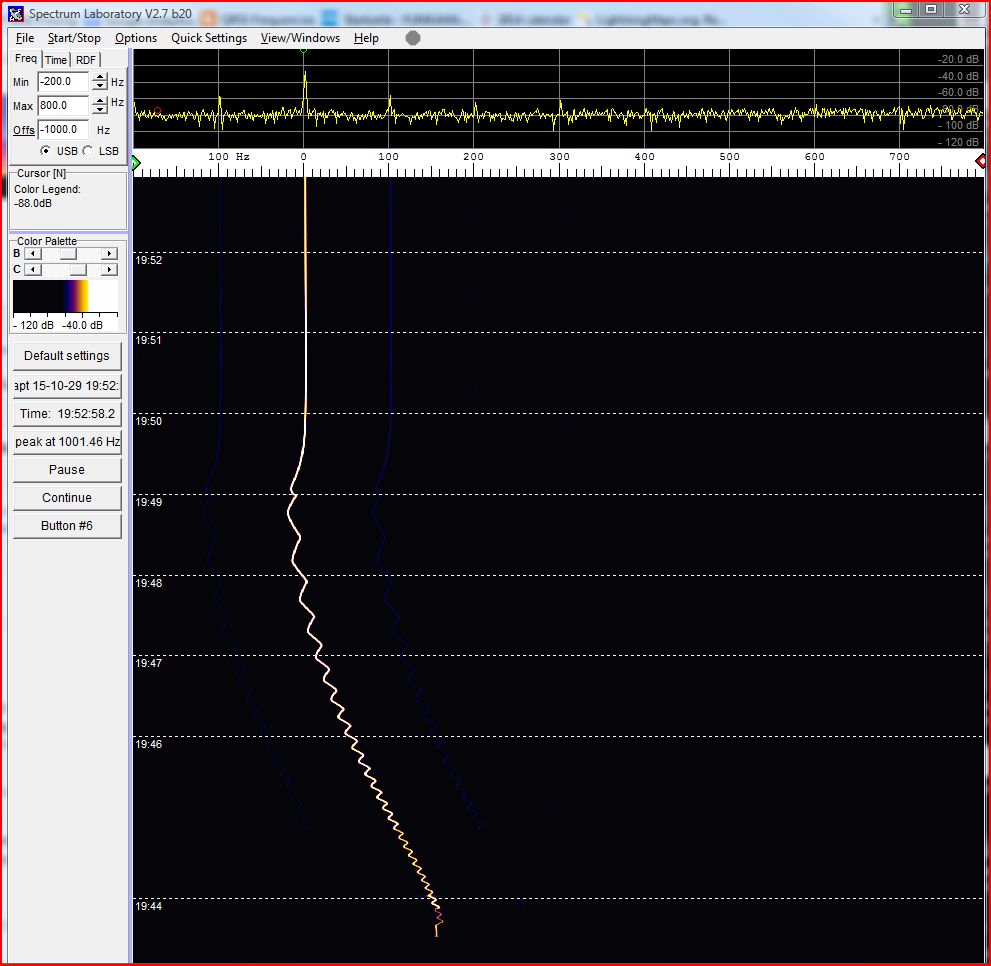
Everything went together fine; I tuned the K3 to 10MHz and used Argo to monitor the output and on first switch-on I could see the 10MHz output and everything looked good, the oven control voltage showed that to be working okay, I could see the 1PPS LED flashing away the frequency lock-on to 10MHz precisely. However, after a few minutes of what appeared to be a “rock steady” output there were a couple of odd “ticks”, these repeated several times and then the frequency would wander up and down and then eventually steady itself! The next photo shows what was happening.

Odd ticks and frequency jumps
At this point I could not read the serial data from the GPS unit so I was uncertain if it was a problem with the GPS unit itself or maybe it was “deaf” and not always “seeing” sufficient satellites. I had also read that early versions of the firmware on some GPS units meant that the units suffered substantial frequency jumps every 30 seconds or so. The GPS I bought had nothing to indicate the firmware revision so I was rather concerned that it might not be suitable. The first thing I needed to do was to be able to understand what the GPS was doing.
I struggled for some time to find some suitable free software that would work with the GPS and run under Windows. Eventually I found a program called GPSMonitor and once I’d worked out how to swap the serial output from Binary to NMEA I was able to confirm that the GPS unit was receiving okay but it appeared to stop working at times. As the GPS antenna was also NOS, I was uncertain how well it was working, plus it only had a very short lead which meant it wasn’t ideally sited. So I ordered a replacement active antenna which meant that I could position it in the clear so it had a better view of the sky.
After sharing my results with Ted, G4ELM and Colin, G6AVK and spending a lot of time troubleshooting this strange behaviour I eventually found a document on James’s web site, that described some GPS units as having a “power saving mode”. This mode not only switches the radio parts of the GPS unit off for up to 80% each 5s period but also the 1PPS and 10kHz get switched off! That had to be it… especially as the GPS unit I was using was a +3.3v operation, low power consumption unit and it wasn’t moving 😉
A quick study of the TU30-D400 Series Data Sheet described how to start the GPS in factory default mode without any of the settings stored in the EEPROM. Fortunately that also meant the power saving was off. Working this way the GPSDO worked as expected without any “ticks” or it wandering off frequency.
This slideshow requires JavaScript.
I now had a working 10MHz GPSDO. To complete the first part of this project I need to fit the parts in an enclosure that would also accomodate the 4-port distribution amplifier and a Raspberry Pi NTP server.

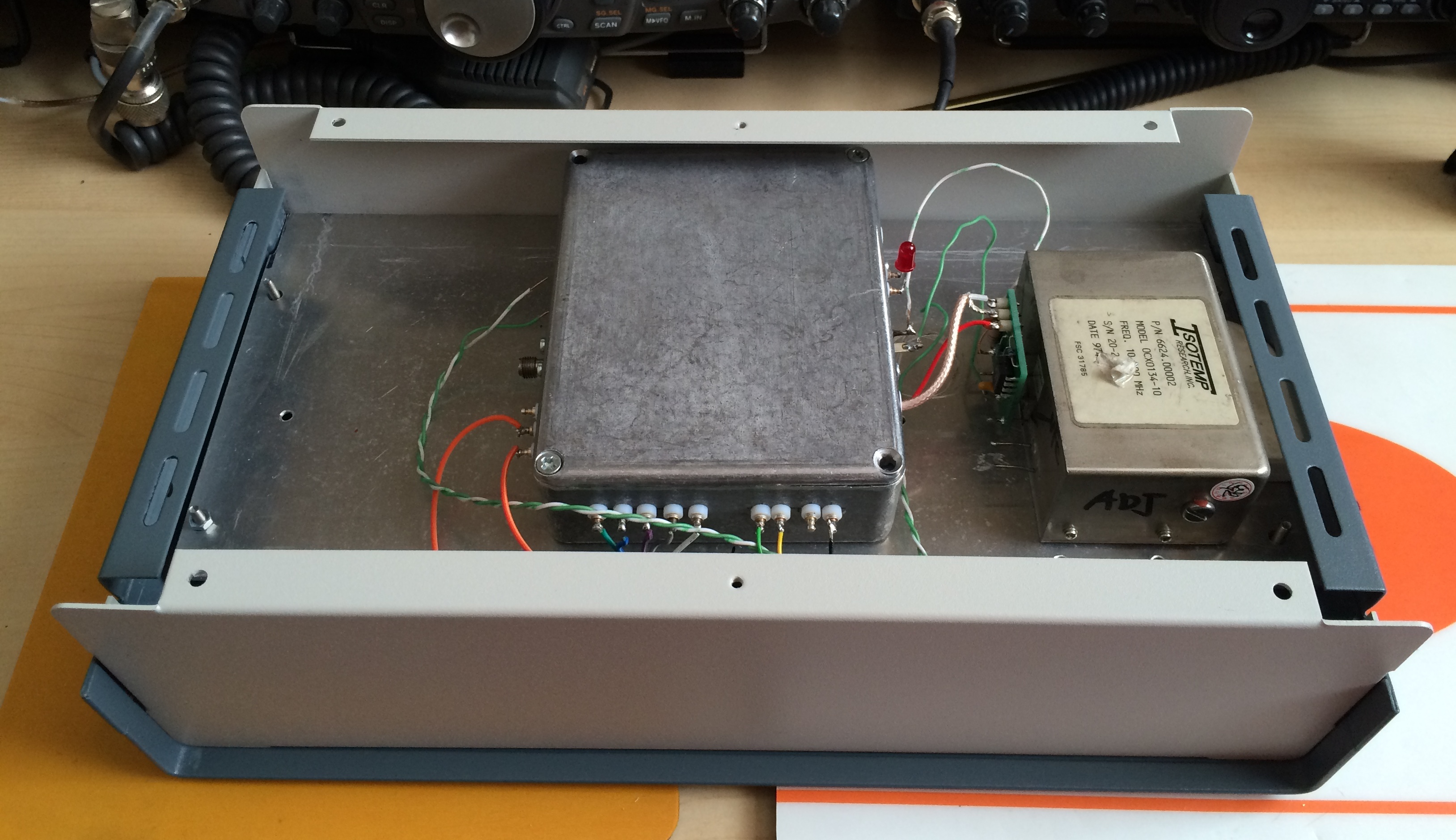
Working out how it will all fit together.
When I built my Anglian 2m transverter I deliberately chose a slightly larger size enclosure than what was really needed. Then if I was to end up with the inevitable “transverter stack”, one size should fit all, and hopefully there would be space available to cover any special requirements for a particular band etc. This is how it all went together:
This slideshow requires JavaScript.
Thanks to Ted, G4ELM who had amongst his many boxes of radio “stuff”, a complete kit of parts to build a DEMI 4-port distribution amplifier; my project was soon sporting this completed board housed in another die-cast box.
The DEMI kit went together without any major grief, although I did choose to build it late one evening after work, so tired eyes meant that some of my SMD soldering could have been better! When it came to testing the outputs, it was a slightly different story. One of the four ports was 50% down on output level. Doing various checks / tests could not pin-point what was wrong; replacing the MMIC did not resolve the problem. So eventually the filter components were replaced one by one and it turned out to be a faulty / incorrect value capacitor!
The next part of this project was to use the 1PPS output from the Navman GPS unit and a Raspberry Pi to provide a NTP server that would provide an accurate time source for any shack PC. Something that’s key to successful Digimode operation. There are many write-ups available on the Internet describing how to configure a Raspberry Pi to provide this time service. I plan to summarise my build as a separate project in the future. The key thing at this time is to note that the two devices both interface together without any problems.
At this point the project does what I set out to achieve; I have an excellent frequency and time standard available for use in the shack.
The 10Mhz reference is currently being used with my SG-Lab TR1300 23cms transverter and as soon as I have the ZLPLL board it will be used to GPS-lock my 2m Anglian transverter.
I tend to leave the unit running for extended periods, typically days on end. From a cold start, i.e. power on it takes approximately 15 minutes for the GPSDO to be locked to satellites, the oven up to tempersture and the PLL locked.
The following two screen grabs show the OCXO at start-up and the frequency “lock-in” and the Raspberry Pi Time service.

GPS / PLL “lock-up”

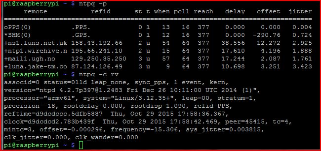
Raspberry Pi time service
What’s next:
- To implement a visual means (LED) to indicate “Lock” state.
- To add an LED to indicate when the OCXO oven reaches temperature.
Acknowledgements:
- J R Miller, G3RUH for his design and PCB’s.
- Ted, G4ELM, Colin, G6AVK and Roger, G4NRG for their help and support.