Anglian 144MHz Transverter

Having moved away from various VHF / UHF transverters and used the TS-2000 and FT-847 “shack-in-the-box” 160m <> 70cms transceivers for many years, with both giving excellent results, it seemed at first a strange decision to embark on a project to build a new 2m transverter. I guess the driver for this was the desire to try and improve the EME system, and with the ease of integrating a transverter with the Elecraft K3 it seemed the way to go.

Having looked at what was available in both “off the shelf” and kit form, I decided to purchase Sam, G4DDK’s Anglian Transverter kit plus the 8W PA kit. These were built and fitted into an enclosure that was sized to also accomodate a future 116MHz PLL board and change over relays / switching for driving additional transverters for the GHz bands.

The following slide show highlights the various build stages through to the finished unit.

This slideshow requires JavaScript.

Both the transverter and PA went together exactly how Sam described in his detailed documentation. I included the 6dB attenuator on the input of the PA as recommended, also to ensure that the Mitsubishi RA08H1317M module runs cool on extended JT65b tests I chose to mount the module and PA circuit board directly on the heatsink. This did then necessitate  some extra metalwork to cut a suitable rectangular hole in the back panel, which can be seen in the following photo.

2015-04-10 Anglian back panel

To reduce the warm-up period and improve stability when first switching on, (important for JT65b operation especially when that new initial contact suddenly appears on the waterfall 🙂 ) I plan to install the ZL2BKC’s ZLPLL  116MHz LO which will be locked with the K3 to a 10MHz GPSDO standard. Until that project and upgrade is completed I have simply added a Murata “Posistor” crystal heater.

The transverter has been setup to provide ~ 3W output, this being just over what is needed to drive my amplifier.  A simple resistive Wilkinson splitter, (using 0805 resistors and SMA connectors) is connected to the 28MHz output. This then enables me to receive on the K3 which is interfaced to a PC running 2 x  WSJT and a FUNcube Dongle  Pro+ which is used with MAP65.

Next Steps:

  1. Label front and rear panels.
  2. Upgrade with a ZLPLL LO


Acknowledgements:

Sam, G4DDK for his excellent kit and after sales support.


Posted in 2M, Anglian TVTR, Blog | Leave a comment

Building a 4m & 6m dual band Yagi.

New 2m, and dual 4 & 6m yagi installation

The following notes will hopefully help anyone thinking of building this or something similar.

All design information and credit goes to Justin, G0KSC and as I’m sure many of you will have  already discovered Justin has a lot of useful build tips on his web site. The actual design I used was the SC6-4-8D

The SC6-4-8D uses stock material so I would expect the element and boom material to be available from most aluminium stockists. I’ve used Aluminium Warehouse before for material to build 2 x 9 element DK7ZB antennas for EME. I now use Aerial-parts of Colchester for most of my antenna parts, fortunately they are located fairly close to me so I can collect (by arrangement). The delivery costs for long lengths of tubing add a significant amount to the overall build costs… it helps if you have another local amateur or some club members who also have an interest in building antennas and can share the cost.  🙂

The all-important element clamps can also be sourced from Aerial-parts of Colchester, as can the mast to boom clamp which needs to be specially ordered for this Yagi as there’s not a lot of space between the D1 and DE elements.

Fasteners are all stainless steel and I sourced them all from eBay – again volume buy helps keep costs down.

The actual antenna build was very straight forward, I invested some time in making a small jig (from a scrap piece of aluminium) to help mark the positions of the holes for the element clamps. A pillar drill makes the drilling of the boom quicker but with the jig and careful measurements the boom can be drilled from both sides – measure twice, cut once 🙂

The plate for mounting the DE was made from some scrap 3mm aluminium sheet I had available.

I used a plumber’s copper pipe tube-cutter to cut the round aluminium tube. I find it more accurate and better than using a hack saw.

I chose to mount the Yagi with the elements hung below the boom, this then allows the balun to also hang below and you then do not need to drill a hole in the boom to allow the coax to pass through – it’s also easier in the future to dismantle the antenna / change the cable.

A tip given to me by another local was to use spacers on the back 6 elements. Due to the different element lengths and the way the interlaced Yagi works people have noticed that the SWR can vary due to the element spacing changing in strong winds. I looked at many different things to find something suitable in the end I found the snap-on cover used on small rectangular cable conduit was ideal in size and weight so I used this to produce four spacers which can be seen in the photo below. I should add I have no idea of the UV properties or longevity of this solution.

4&6m yagi - spacer for reflectors 2014-06-08 15.29.484&6m yagi - spacer for 2 x D1 & 2 x DE 2014-06-08 15.12.59


In summary the construction was very easy and can be done with what I would consider to be the average  DIY tool kit. The hardest part was making the choke balun – I am not kidding… I used RG-214 and trying to wind five turns of that while keeping the cable-ties in place and then cable-tying it all together single handed is not easy.


Choke Balun 4m-6m yagi 2014-05-01 13.10.56Once again Justin has some good instructions on his web site on how to wind a choke balun.


I hope to publish some SWR graphs of the antenna in the future….

Update:  I have had an opportunity to use an MFJ-259 SWR Analyser to run a few very quick tests on the antenna. The results showed a good match on 6m, on 4m resonance was right at the bottom of the band (ideal for DL band plan  🙂  )  and on 70.200 MHz the SWR was measured at 1.5:1  I believe this “shift” is due to adding the PVC strips. More time is needed for further investigation…  and for me to invest in some new test gear!

4m & 6m dualband yagi SWR

I should also add that I have no business association with any of the  companies listed other than being a  satisfied customer.

Acknowledgements:

Justin, G0KSC for the antenna design.


Posted in 4M, 6M, Blog | Leave a comment

QRSS – Ultimate3 MEPT

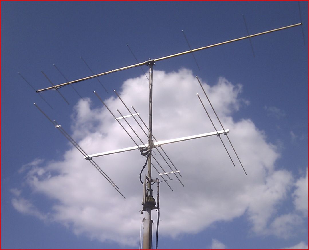
Having set up an Argo based Grabber to support some QRSS tests I was soon keen to see what I could do with a relatively simple very low power transmitter, or Manned Experimental Propagation Transmitter (MEPT), and my W3DZZ inverted-V dipole.

There are many designs / kits available on the Internet, I chose to build the Hans Summers QRPLabs latest Ultimate3. This is offered as a single-band kit of parts that will allow many different modes to be used and by purchasing additional plug-in LPF kits it’s possible to use the Ultimate3 on 12 different HF / MF bands.

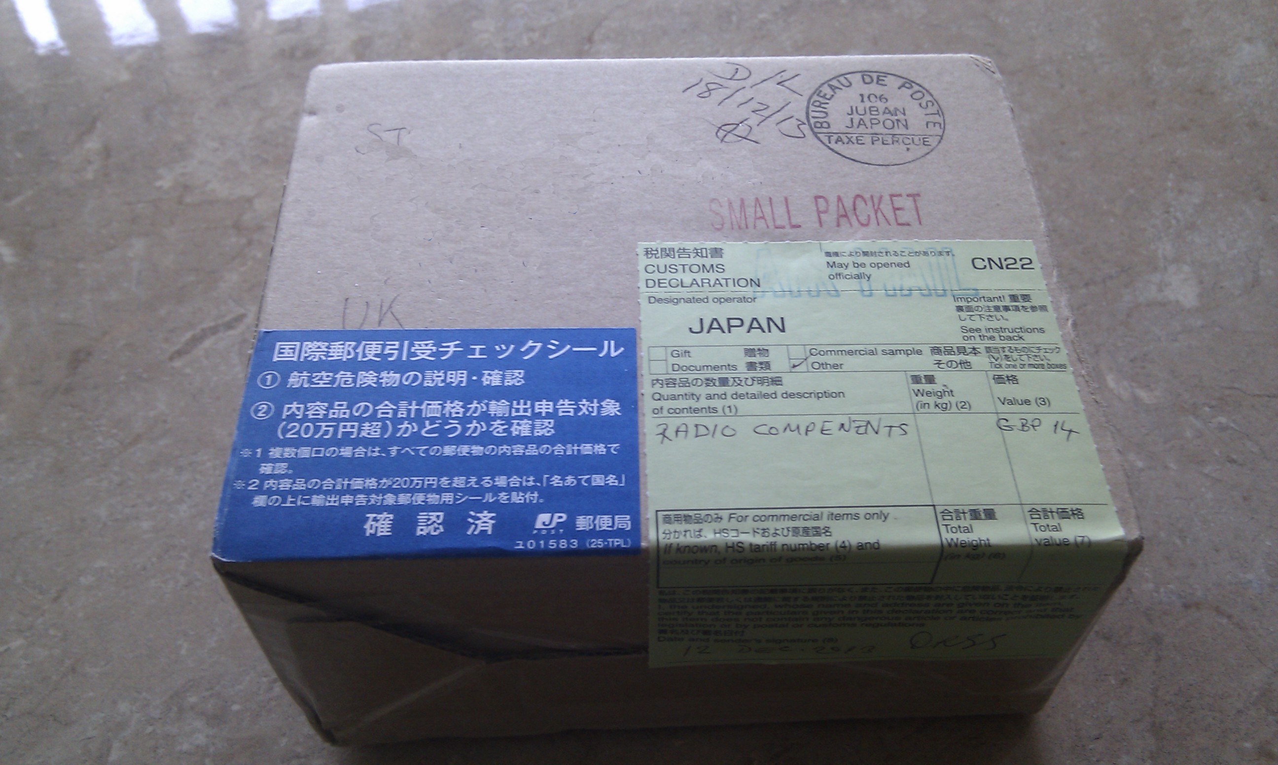
I placed an order on 29/11/2013 for a kit with 30M LPF plus one additional LPF for 10M. The ordering process was very straightforward and an email confirmation of my order was received later that day. Having placed my order I was naturally keen for the kit to arrive.  On 12/12/2013 I received an email telling me that the kit had been shipped and finally on 18/12/2013 the package arrived!

Ultimate3 PackageMuch to my surprise the kit of parts was shipped from Japan. The kit was extremely well packed, and the various bags of components clearly labelled.

It’s worth pointing out that although the kit of parts is fairly small the packaging does not allow the box to be posted through an average UK letter box so if you are not in at the time of delivery you will most likely end up having to collect from your local Post Office (as I did!)

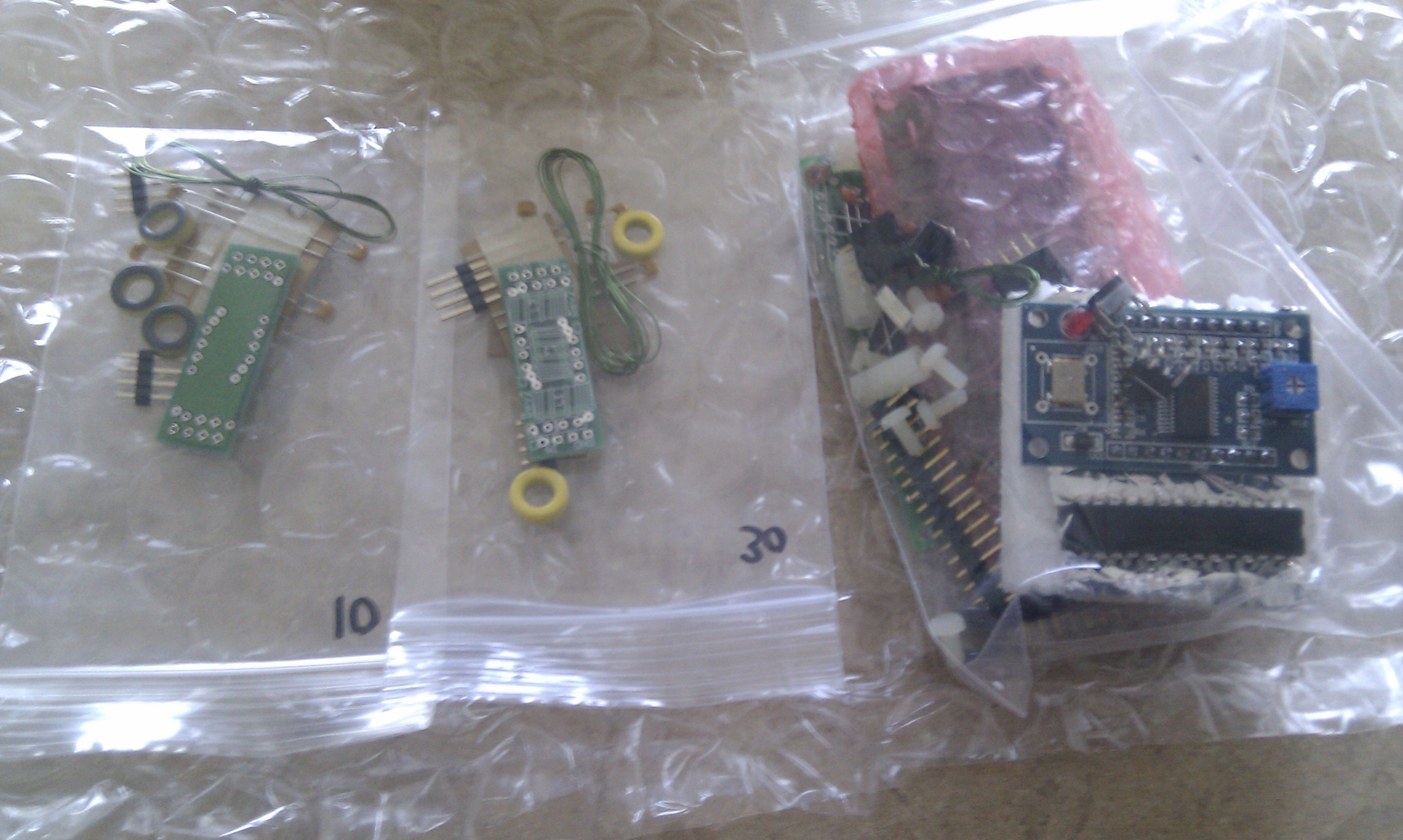
Here’s what the box contained:

Kit of parts 2013-12-19Two LPF kits (for 10M and 30M) plus the Ultimate3 kit including DDS module.

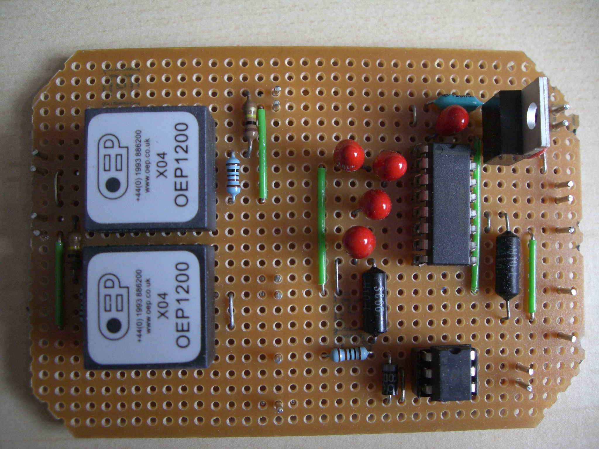
Being very keen to get going I decided to build the Ultimate3 kit and just the 30M LPF kit.  I found the downloaded instructions to be clear, the kit of parts was complete and everything went together without any problems. I chose to mount the toroid on the main board, horizontal i.e. flat on the PCB; this kept it well out-of-the-way of the LPF board. I also used some “super-glue” to stick the toroids in place on the LPF board

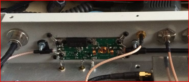
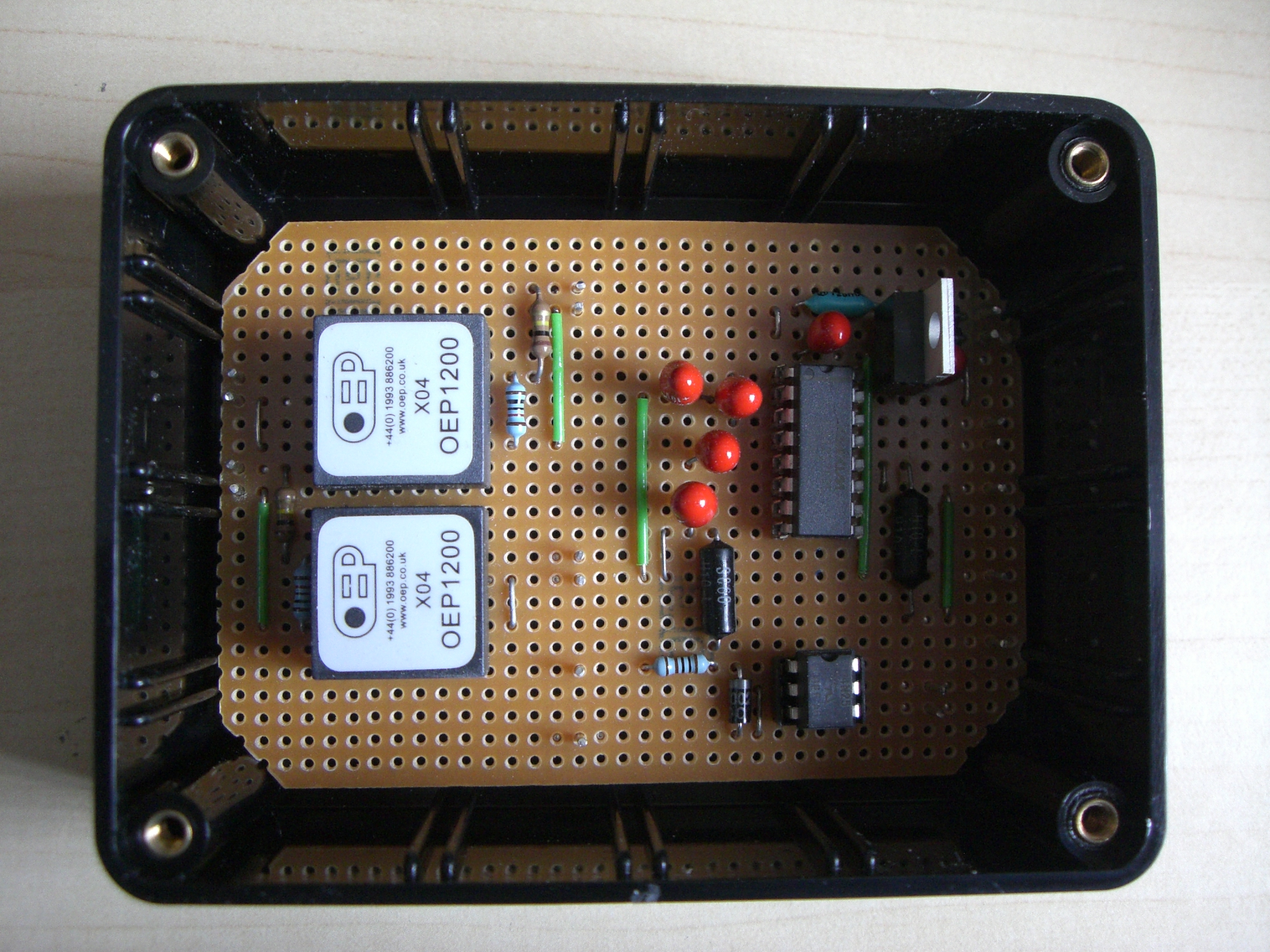
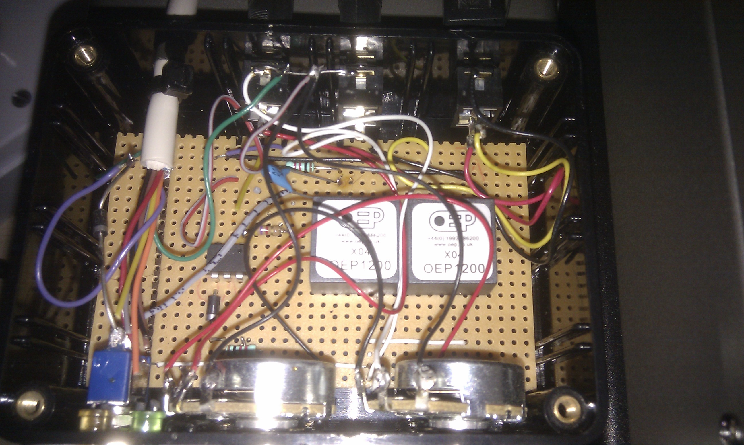
Here are some photos of the completed boards:

This slideshow requires JavaScript.

The Ultimate3 requires a 5V DC power supply. Being keen to get the unit going I decided to use an old “phone charger”-style PSU found in the junk box with a small outboard regulator to reduce the 7.5V output of the PSU down to 5V.

Following the recommendations in the assembly instructions, I glued a fairly thick piece of copper to the DDS crystal housing to act as a heatsink and improve the frequency stability.

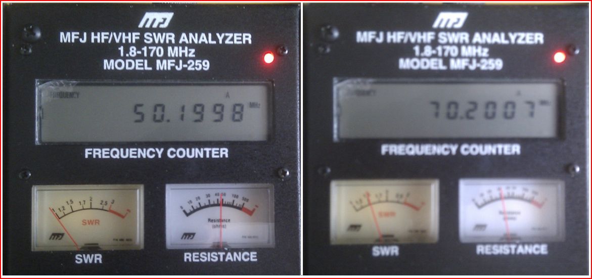
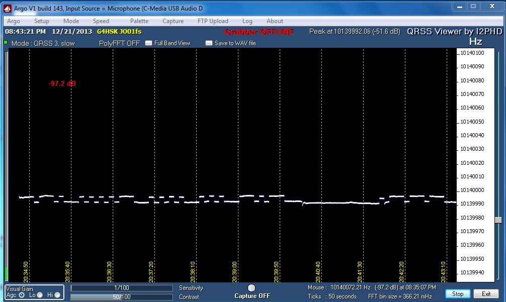
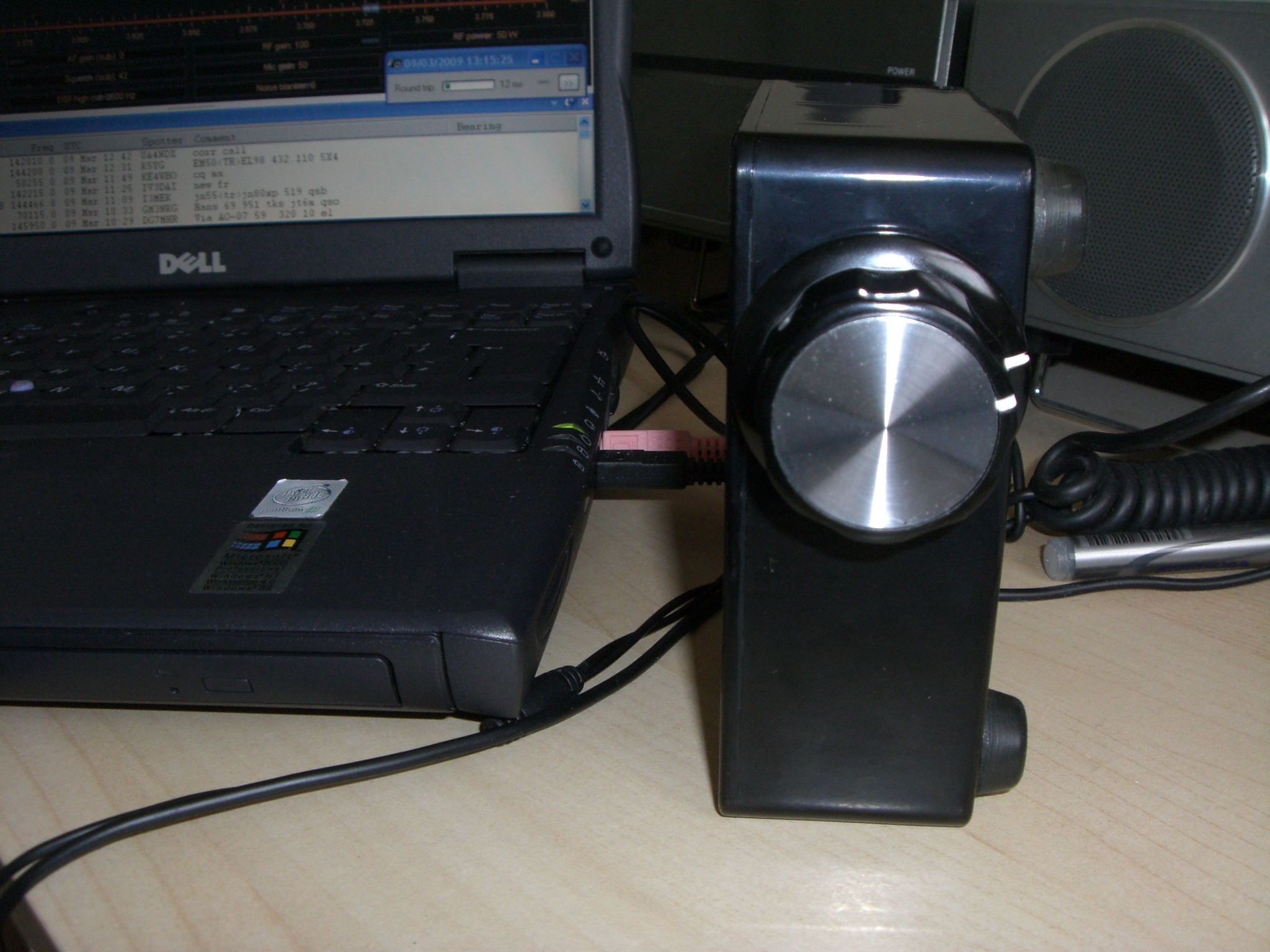
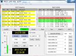
With the Ultimate3 connected to a dummy load the 5 V supply was connected and the LCD lit up, a quick adjustment of the small pre-set and I had a nice white on blue display.  The basic settings were configured and I could hear my signal on the shack receiver. The next stage was to check the frequency stability and signal quality, this was done using Argo (see QRSS Grabber pages for more info on Argo)

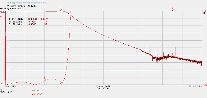
The following photos show the results during the initial setup:

U3 First power up after configuration 2013-12-21

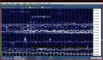
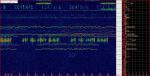
Ultimate3, power on after config, initial drift from cold,

U3 after configuration 2013-12-21

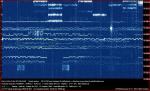
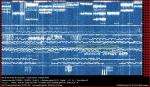
Ultimate3 after configuration. Showing signs of instability.

Here you can see that the signal strength was far too high for my receiver / Argo, even without an aerial connected to the receiver. You can see that the frequency dropped by about 20 Hz from switch-on but settled very quickly. By reducing the Argo Sensitivity setting to 1/100 and reducing the RF gain on the receiver (FT-847) I got a much improved trace, but it still did not look that great. I suspected that the 5V supply was possibly the cause of this and applied some extra decoupling plus a large clip-on Ferrite. This made a slight improvement but you could still see some frequency instability at the start of some characters. I then remembered that I had an old 0 – 30V test lab-quality PSU squirrelled away somewhere. This is  now back in service and has resolved the problems I was seeing.

U3 G4HSK trace running on Farnell PSU 001 2013-12-22

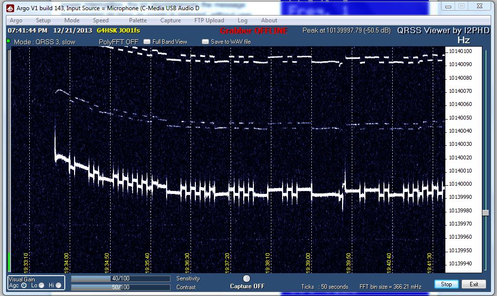
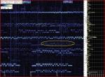
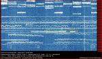
Ulimate3 running on Farnell PSU – much improved trace.

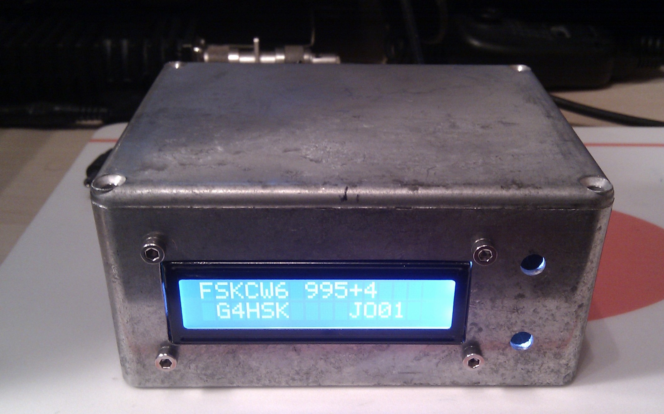
The next stage was to box up the Ultimate3; here I used what has become the HSK standard project housing, an Eddystone die-cast box. The photo below shows the end result, albeit without the two push-to-make switches as my spares box let me down and they were not available at the time!

2013-12-22 19.33.34

Possibly the most difficult part of setting up the Ultimate3 was determining what frequency to use within the very narrow bandwidth used for QRSS transmissions. To do this I checked a number of Grabbers (both local and distant) at various times of the day and night (using their archives) to find a spot where there was the least chance of “sitting on top of” (or under!) another MEPT. Obviously there’s no guarantee of this, but by doing your homework you can reduce the chances of this happening.

Having set my chosen frequency I ran the Ultimate3 into a dummy load overnight on “soak-test” to ensure that the frequency stability was acceptable and the signal trace looked okay. This test was passed and I ran the Ultimate 3 on the air for the first time on 23/12/2013 running FSKCW6 on 10.139.995  For the next 24 hours I was checking any active Grabber I could find to see if my signal was being captured anywhere. My first “report” was from Colin – G6AVK, my local QRSS expert   🙂

U3 Seen by G6AVK 2013-12-24

After this initial 24 hours and careful observation of signals around “my” chosen frequency I decided to move very slightly lower to 10.139.985

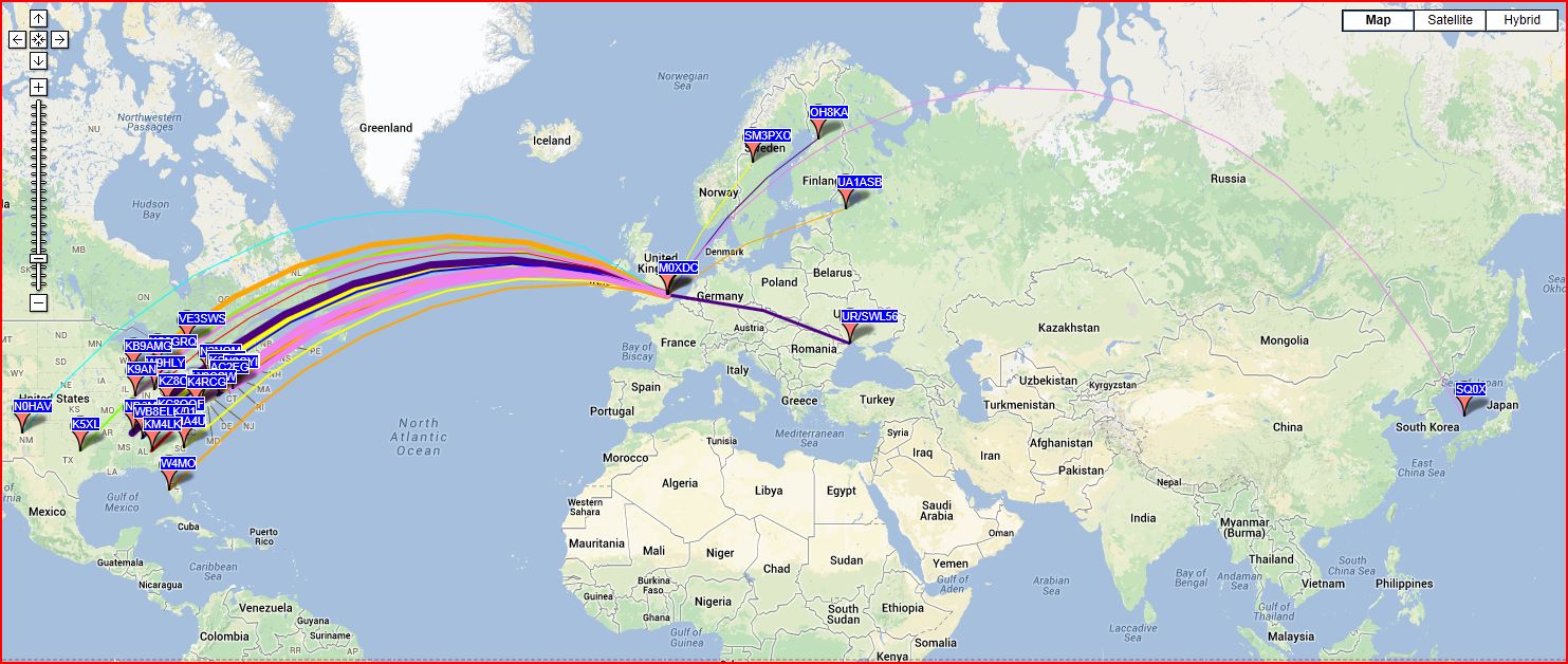
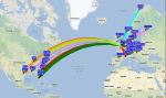
As I write this, the Ultimate3 has been running for 4 days non-stop.  The kit in standard form (single BS170 and 5V) produces approximately 150mW RF output on 30m. Taking ATU and cable losses into account I guesstimate that somewhere between 50 – 100mW is reaching the feed point of the W3DZZ, which itself is far from an efficient aerial on 30m, but even with this setup my signal has been “seen” in Florida!  🙂

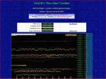
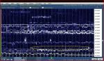
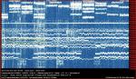
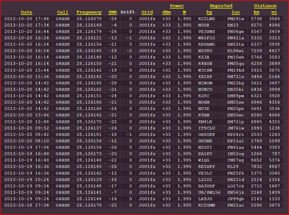
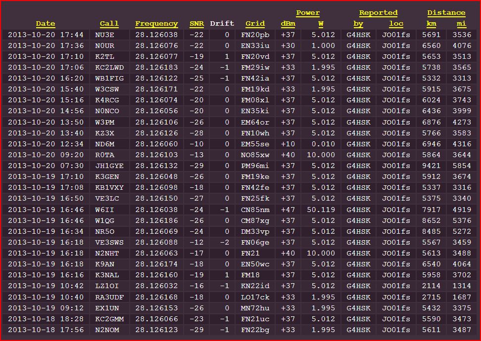
The images below shows a selection of  captures taken over the first few days from various Grabbers active on 30m.

Summary

After a very frustrating wait for the kit to arrive, I have to say that it was well worth the wait. I’ve had tremendous fun over the holidays putting it all together and seeing where my signal could be “captured”.  If you do happen to see my callsign appear on your Grabber then please do let me know. Any reports would be much appreciated.

What’s next?

  1. To complete the 10m LPF and run some tests on that band.
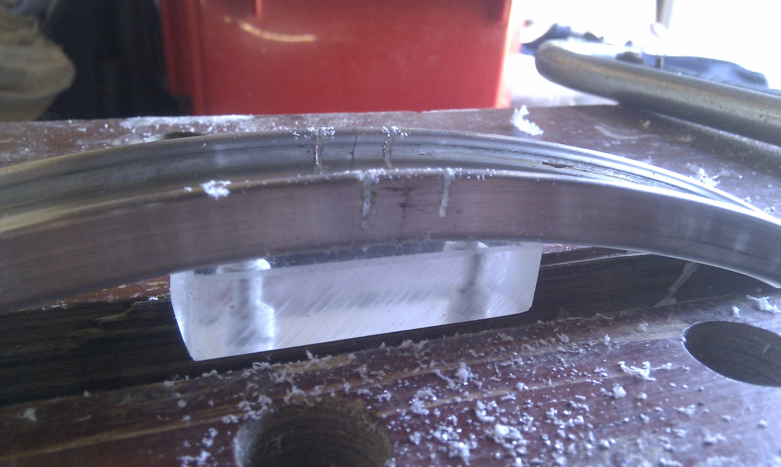
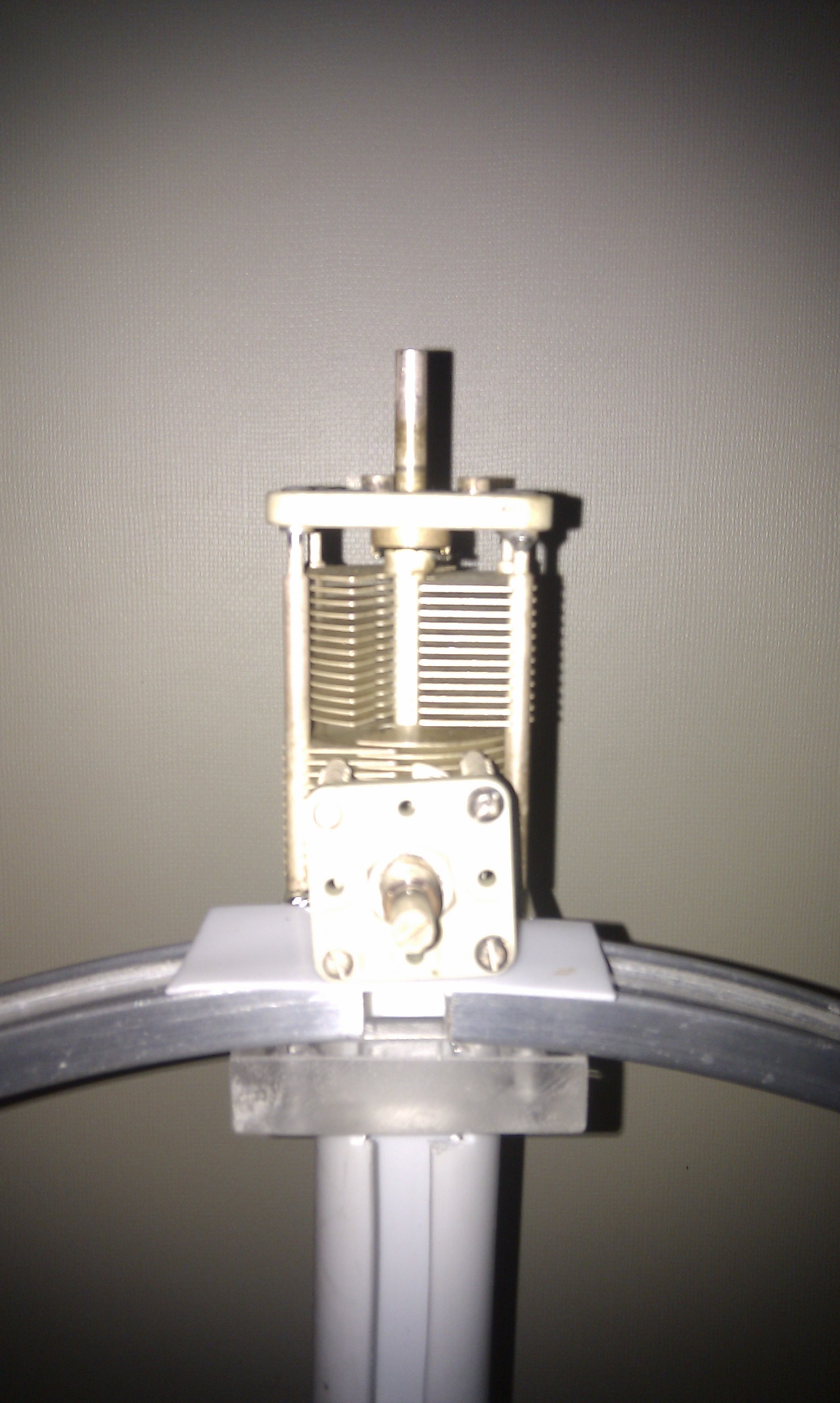
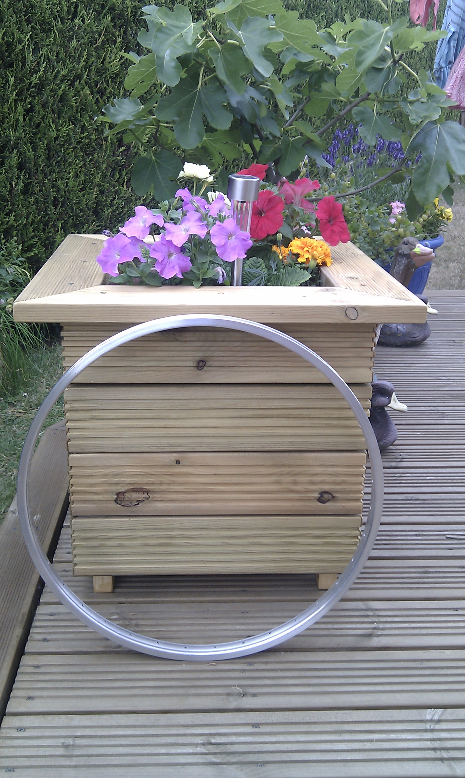
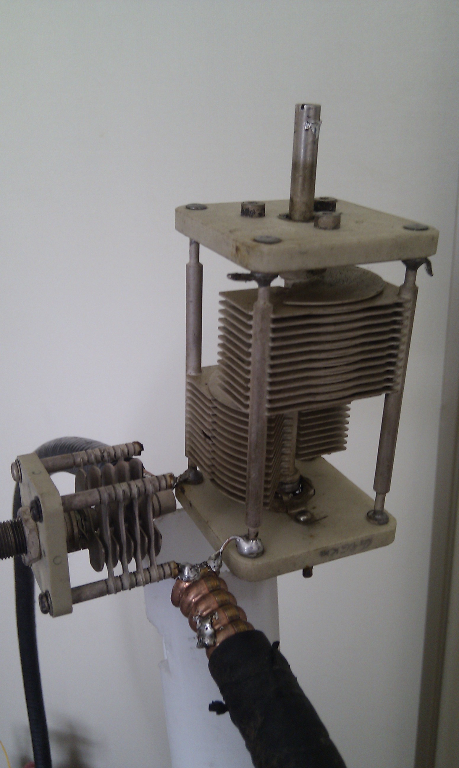
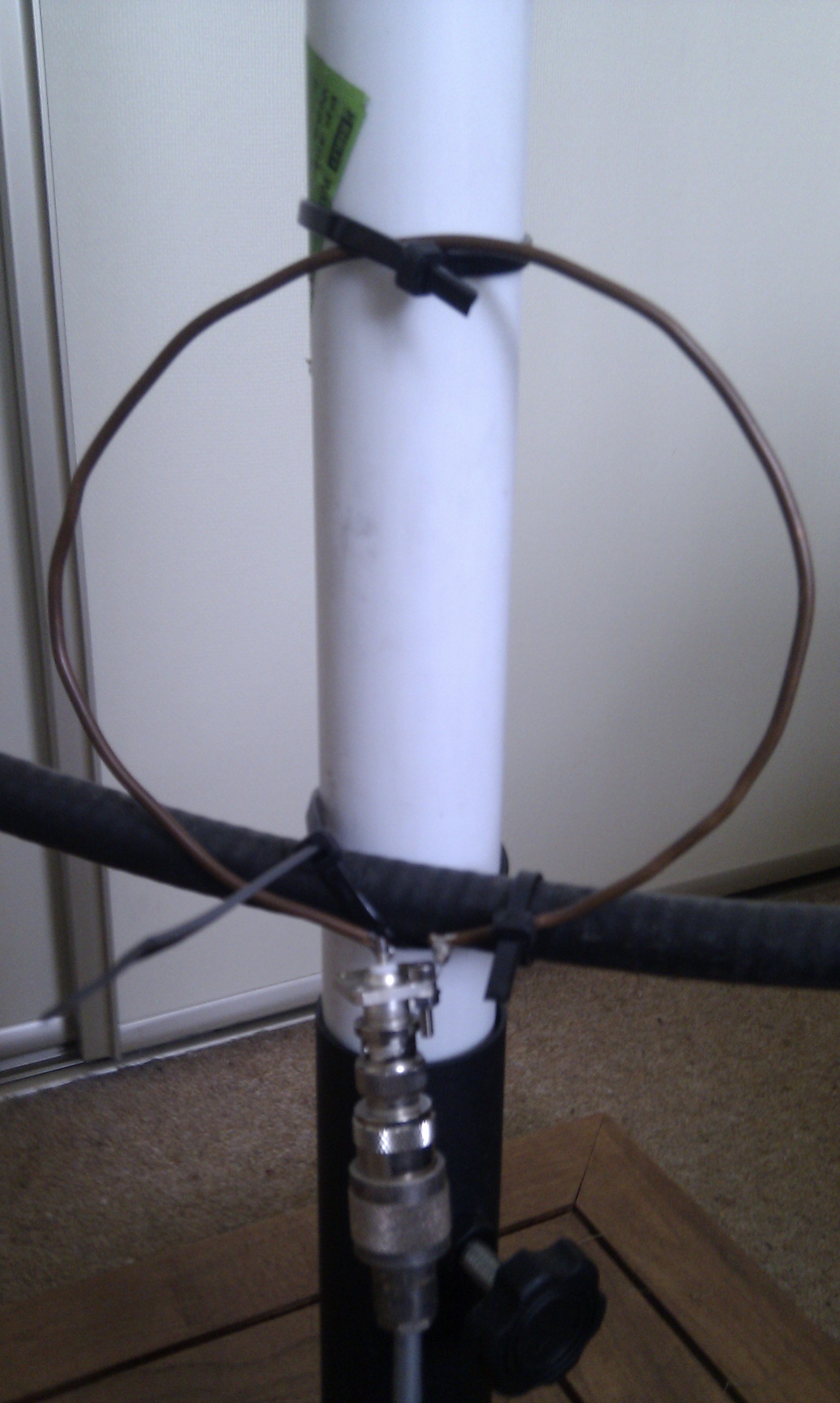
  2. Try the Ultimate3 with the 24″ bicycle Mag Loop.
  3. Add a GPS module to improve timing and stability.
  4. Try WSPR
  5. Install the switched LPF board when it’s available.


Posted in Blog, QRSS / WSPR / QRP | Leave a comment

USB Tuning Knob

I have used a number of different PC programs to control my FT-847 and TS-2000 transceivers and the one thing that I found I missed when driving the rig remotely was a conventional tuning knob. Yes, the mouse could be used to click on a frequency or by  using a combination of the buttons and moving the mouse or scrolling with the wheel I could tune across the band, but to me it just didn’t feel right.

One day it occurred to me that if I could possibly attach a spindle and knob to the rotary encoder / wheel of a mouse it might make a simple and very cheap “conventional” tuning control. I make no claims for originality as I have seen this idea elsewhere on the Internet.

I had a number of old USB mechanical roller-ball mice in the junk box, these had all been replaced with newer optical devices so they really had no further use… but this was to change.

The upper casing of the mouse was removed, along with the hard rubber tracker ball. The plastic base of the mouse was also reduced to a smaller size, taking great care not to touch or damage the mouse printed circuit board.  Electrically the mouse was untouched, the original USB lead, internal connections etc. all remained exactly as they were.

The photo below shows the idea:

CIMG2063

To rotate the mouse wheel a standard 1/4″ drive shaft and large tuning knob were needed. They were fitted as shown in the photos.

The following photo, taken at an angle, shows the mouse base glued in place.

CIMG2067

 Here’s the finished unit:

CIMG2069

I found that the tuning control worked really well, it did however tend at times to skate across the operating desk as there was no real weight to the unit. To overcome this  a heavy weight was glued in place inside the plastic enclosure.

The USB tuning control works really well, it is used in addition to a normal mouse. It is in effect working in parallel, so once the mouse pointer is positioned on the tuning dial using the standard mouse, the tuning can then be done using the new “conventional tuning knob”.

I should point out that I have not opened up different makes of mouse to see how much they vary in construction. The first one I selected was ideal for my intended use as the roller wheel spindle was plastic, there was plenty of clearance for the shaft and no danger of any electrical or physical contact between the new spindle and any of the mouse circuitry.

Posted in Blog, SDR | Leave a comment

24″ Bicycle Rim Mag Loop Update

My first tests using the 24″ aluminium bicycle rim did not work out well. This was, as you may have already read elsewhere, due to problems with the Faraday coupling loop that I was using at the time.

Having had extremely encouraging results using the LDF4-50 based loop I decided to try the bicycle rim again but this time I simply used the working coupling loop from the LDF4-50 loop.

So here’s a photo of the 24″ loop:

Working Bicycle Rim Mag Loop

I made two cuts in the rim  opposite the hole that was left by the inner tube valve to form a small 1/2″ (12.5mm) wide gap. A small section of Perspex was then used to bridge this gap to maintain shape and rigidity. The same method of tuning was adopted as used on the larger loop i.e. a large split-stator capacitor for the coarse tuning plus a small butterfly capacitor in parallel for fine tuning. The coupling loop was a very simple single turn of copper micro-capillary tubing as used on boiler thermocouples; this was formed into a 5″ (125mm) diameter loop.

Cutting the rimTuning Caps

To tune the loop, I normally set the small (butterfly) capacitor so it’s half in mesh and then adjust the large capacitor to peak the received signal, then using a very low output (typically 1W) I adjust the small capacitor for minimum VSWR on transmit.

This loop tunes approximately 20 – 35MHz and is used mainly on the bottom end of 10M for digi-mode contacts and experiments (WSPR, QRSS etc)

The results with this size loop, setup on a stand, indoors, have been very encouraging, running WSPR tests with less than 2W output have produced the following results:

2013 10M WSPR 24 inch Mag LoopThis map shows the results running WSPR on 10M.

2013-10-20 WSPR 10M 2W Bicycle Rim Mag Loop - ReportedThis shows the results on transmit on 10M.

2013-10-20 WSPR 10M 2W Bicycle Rim Mag Loop - HeardThis shows how well the loop received on 10M

WARNING:  Because of the very high Q, some capacitors can arc over at power levels as low as 10 watts. Remember also that even with only a few watts of RF power, magnetic loop antennas produce very high voltages across the capacitor(s) and can cause nasty RF burns if touched while transmitting.


Posted in Blog, Magnetic Loops | Leave a comment

Magnetic Loop Antenna

I’d spent some time reading various articles describing the construction of magnetic loop antennas. The reason for this interest was that my son (2E0KGG) had moved to a new QTH and to help get him active on one or more of the HF bands we needed an antenna design that was suitable for use indoors or on a balcony.

Also around this time the station manager (XYL  🙂  ) had me sort out the garden shed and one of the items of junk to be discarded was an old bike wheel. That was until I remembered the article I’d read about using an alloy rim of a bike wheel to make a loop antenna! Needless to say not all the parts of that wheel went into the skip.

I now had something to base my first magnetic loop antenna on, what follows is the results of my experimentation, both good and bad. This is still very much a “work in progress” project and will be updated as new things occur.

The cleaned up 24 inch rimWith some careful cleaning I had a basis of a neat looking antenna…

For mechanical strength and to maintain rigidity I used some 1/2″ thick perspex to make an insulator to bridge the slot that would be cut into the rim. Also across this would go the air-spaced capacitor.

Having had a quick search of my boxes of “old radio stuff” I found a very large air spaced capacitor. Ideally I wanted a split-stator capacitor but what I found was a normal variable capacitor but it would do for an initial test.

The first 24 inch rim loopThe next requirement was  some form of support, here I used a length of white plastic tubing sold in DIY stores as “waste pipe” and the base off the garden parasol!

Having sorted the main loop out I then needed to make the primary feed loop. For this I used a length of RG213 to form a Faraday loop. This proved to be a little bit of challenge to join together at the top of the loop and still maintain the circular shape given the thickness of the cable. However with use of insulating tape and suitable heat shrink tubing I had something that looked good.

I think those last two words were fitting for what happened when I tried the loop.

Not having an antenna analyser I knew that the only way to see where the loop was resonating was to listen for a peak in receive noise so I connected the antenna to the radio and tuned to 10M. A quick swing of the capacitor resulted in no noise peak, switching to 12, 15 17 and 20M also gave the same result – it didn’t work!

Having spent so much time making the Faraday loop and only having the one capacitor to hand I decided that the thing to change would be the loop. Bigger has got to be better – right?  So I  replaced the nice round alloy rim with a quickly hand formed 1M diameter loop made from LDF4-50 cable, I then repeated the tests and it still didn’t peak on any band!!!

At this point I decided it had to be the primary coupling loop, it couldn’t be anything else. So I replaced the coupling loop with a simple loop made from 1/8th copper wire  soldered directly to a BNC socket, connected this to the radio and repeated the tests. SUCCESS… the loop tuned on 3 bands. I now had something that was “working” and I could start to experiment with.

The next modification.

I found that I could peak the receive noise but not having any form of slow motion drive  the tuning was very critical so improvements were needed in that area. Digging deeper into the boxes of “old radio stuff” I eventually found two split-stator capacitors and a wide spaced butterfly capacitor which were all crying out to be used.

I experimented with the two split-stator capacitors and found that one of them would allow the loop to tune from 30M through to 10M. To provide the fine tuning I connected the butterfly capacitor in parallel with split-stator capacitor.

The current working configuration.

The following photos show a Magnetic Loop Antenna that is a complete lash-up in terms of the mechanical construction yet it is giving some surprising results.

2013-07-22 11.34.38Tuning is very simple, the butterfly capacitor is set to 50% mesh, the large split-stator capacitor is then adjusted for peak in receive noise and then finally on transmit the butterfly capacitor is adjusted for minimum SWR.

Coupling loopThe simple wire coupling loop works across the 30M to 10M range giving an SWR better than 1.2:1 I have not experiment at all with this loop in terms of its size, positioning or shape.

The final photo and gallery show the complete loop, and some of the results obtained using it inside the shack running a maximum of 5W output power to a 20M run of RG58 with a simple 5 turn RF choke before the BNC connection on the coupling loop.

Mk 2 Heliax Loop


WARNING:  Because of the very high Q, some capacitors can arc over at power levels as low as 10 watts. Remember also that even with only a few watts of RF power, magnetic loop antennas produce very high voltages across the capacitor(s) and can cause nasty RF burns if touched while transmitting.


Some screen shots of results running various data-modes on 20M and 30M

What’s next?

Having had such good results the next steps are to:

  1. Improve the connections between the LDF4-50 and the capacitors using copper strip.
  2. Weather proof the tuning capacitors using a plastic enclosure.
  3. Experiment with the primary loop coupling and weather proof the feed point.
  4. Try a different coupling loop on the bike rim loop.
  5. Build an Arduino / RaspberryPi based control unit to remote tune the loop.
  6. Build an LDF5-50 loop for 40m with trombone tuning.


Posted in Blog, Magnetic Loops | Leave a comment

DigiMode Interface

The following photos show the homebrew interface. More details to follow…

DigiMode Interface

Interface boxed up

Interface completed

Posted in Blog, QRSS / WSPR / QRP | Leave a comment

4M Low Pass filter

The following photo shows the home made filter based on OZ2M’s design.

4M LPF

At the time I was gathering the parts to build the LPF I happened to spot a listing for four 56 pF door knob capacitors on a well known auction site with a buy-it-now price. Fortunately I was at the right place at the right time to purchase them so the biggest challenge in terms of parts was sorted. I found that an aluminium Eddystone Die-cast box (120mm L x 95mm W x 57mm H) was an ideal size for this project.

Having only very basic test equipment available to me I was very careful to follow the dimensions and layout as described on OZ2M’s site. By looking at the 2nd harmonic I was able to check and verify that the filter was “working” but I had no means of plotting the filter curve and accurately measuring its characteristics.

After using the filter for some time I got talking to John, G4ZTR regarding using a single feed, interlaced 4m and 6m dual band antenna with the FT-847 and how the filter would work in that setup. John was of the opinion that the filter could be used in-line on both bands. To confirm this he very kindly offered to check my filter on his network analyser.  🙂

G4HSK 4m filter smHere’s the plot (full size) that shows that the 4m LPF is performing as intended.

The key points of interest being: 0.14dB through loss at 4m (and 0.30dB at 6m) with around 60dB attenuation on the third harmonic.

This has confirmed that this LPF design can be built without any special test equipment and produce good results. It should also work fine with my planned change to a 4m / 6m dual band Yagi

Posted in 4M, Blog | Leave a comment

2 x 8 ele I0JXX

Having had excellent results with a single yagi I wanted to add an additional antenna to get some extra gain on both TX and RX. I originally planned on using a second 9 ele DK7ZB but changed my mind when I started to look at some of the “challenges” of baying two antennas (or using X-pol!).

I wanted an installation where the main cross-boom did not require any additional bracing and also the antennas did not need any under or over bracing to keep their booms straight. In hindsight, when I built the DK9ZB’s had I used smaller diameter material for the elements and perhaps a thicker section boom I would possibly not have needed any additional support to stop them sagging.

After looking at what antennas people were using and what was available (both to homebrew and purchase) I opted for 2 x 8 element I0JXX yagis. Getting the new antennas was the easy part, fortunately “Aerial-Parts of Colchester” are UK stockists and they are only a short car journey from here, the biggest challenge was what to use for the main cross-boom. It seemed that neither 43mm aluminium thick walled tube or suitably thick walled fibre-glass tube were generally available in lengths < 6M and at a reasonable price…

I did eventually find a source of material for the cross-boom and the photos below show the end result:

I used the maximum diameter of aluminium tube that the G-5500 can take in its standard form;  in the UK this was 1-5/8″ (approx. 42mm dia.) and I chose 1/4″ (approx. 6mm) wall thickness. The remaining sections of the cross-boom are made up of 50mm diameter, 4mm wall fibre-glass tube. The aluminium and fibre-glass sections are joined together using 2 x 5mm bolts.

The total weight of the cross-boom, without any additional hardware was 5.4 kilo.

Here you can see both sides of the cross-boom and one of the I0JXX yagis. The cross-boom does not require any additional support bracing.

The coax feed must not run in-line with the yagi elements. this photo shows a large loop of coax before it is strapped to the boom.

Here you can see the new updated driven element on the 8 element I0JXX yagi. The original “T” feed has been replaced with this new design.

The cross-boom continues to support the two antennas with hardly any noticable sag.

As mentioned earlier, sourcing the fibre-glass tubing proved to be a real challenge. After much searching on the Internet I found a local company (Anglia Composites) that sells a range of cut length GRP tubing as part of their modular handrail system. I purchased and collected from them 2 x 1500 mm lengths of tubing in grey.


Posted in 2M, Blog | Leave a comment

IC-735

I purchased the IC-735 back in the 80’s, it has always been a favourite rig of mine and has spent most of its life as the prime mover for my 50, 144 and 432 Mhz transverters. I retired the rig a few years back when I got the TS-2000 but recently resurrected it after my son, Kristian, 2E0KGG, obtained his licence.

After bringing the rig out of retirement I found it had three small faults that required attention. Two of the dial lamps had unfortunately failed, the AF-gain control was very noisy and the VFO was slightly off frequency.

None of this really worried me, I thought I’d simply source a new AF/RF control, some LEDs for the display and fix all three “issues” in one hit. After much research it would seem that the AF/RF twin POT is no longer available, so I was left to hope that a good spray of switch cleaner / lubricant would do the job!

I read many articles describing replacing blown bulbs with LEDs and by using different colour LEDs the rig could be given a completely new look! I also discovered that the four small bulbs used to illuminate the front panel on the IC-735 each had a small plastic “hood” to give the characteristic green display. One of the sites I visited had a photo of an IC-735 that had been fitted with “white” LEDs and it looked really good, so I decided that I would do the same.

These four photos show the location of each of the original bulbs.


It was fairly easy with a small soldering iron and tweezers to remove them. By carefully studying the track layout and double checking with a meter I knew the +ve supply rail. Each bulb was replaced by a “white” LED and series resistor. I experimented with a number of different value resistors to get the desired brightness. Note that the “dial lamp brightness” pot accessed from the side of the rig didn’t provide much adjustment. Unfortunately I do not know the specification of the LEDs used as they were once again from the “spares box”.

Once all four LEDs were in place and everything checked I gave the AF/RF POT a spray of cleaner / lubricant and left it overnight. The next morning I gave it another spray of cleaner and then set about the frequency adjustment. Fortunately ICOM made this a fairly easy adjustment and it’s well documented in the manual.

There was just one thing that wasn’t expected…

I knew about the green coloured “boots” on each bulb and I had definately removed all four bulbs plus “boots” and replaced the bulbs with four “white” LEDs all from the same un-opened pack yet the meter illumination still had a yellow / green tint! This was not apparent in the photos I’d seen previously and I could not see any obvious colouring to the meter casing…

At the end of the day I don’t find it a big issue, everything is working fine, the rig is performing very well, and it’s also interesting to see if any visitors to the shack ask about the difference…  🙂

This photo was taken in poor light with a phone camera, so the display does appear rather bright on the outer edges. I have since read that rubbing the surface of each LED with abrasive paper can help diffuse the light, so maybe next time I have the covers off I might be tempted to have another go (and change back to green?  🙂  )

Posted in Blog, IC-735 | Leave a comment