

My experiments with the small 65cms OS dish encouraged me to push on with the work needed to get the 1.2m dish up on the mast. The EchoStar dish had sat in my shed gathering dust for several months. I decided to mount the new dish in the same way as the smaller dish. So a new heavier duty support was needed.
After much measuring, cutting and drilling I ended up with the following:

There is still work to be done. I plan to upgrade the feed support arms with a much stronger bottom support arm to support a new TVTR and PA enclosure. The side support arms will also be spaced further apart at the feed end to allow for different feed systems to be fitted. I hope also to be able to fit the QO-100 feed alongside the 10GHz system.
The new dish did not come with its original LNB and the feed support bracket had clearly undergone some repair with a spot of welding.

Misaligned LNB clamp
I have a laser pointer mounted into a 40mm diameter 3D-printed holder. This was fitted into the original LNB clamp and a few basic feed alignment checks made.

Laser pointer in 3D-printed holder
The laser spot on the surface of the dish was way off the centre-line of the dish and lower than I had expected.

Original repaired LNB holder pointing way off centre-line.
The welded on clamp was removed using an angle-grinder and I refitted the laser-pointer how I expected the LNB to be positioned. This time the laser-spot was on the centre-line and 3.75cms above the physical centre point of the dish surface.
I entered the physical attributes of the dish into one of the off-set dish calculators to get the focal point of the dish. Using a length of cord with knots tied at the three key points I was able to establish that the “front” of my home-brew feed was roughly in the correct place. Not knowing the exact specification of the dish, specifically the designed off-set angle I wasn’t sure where the laser spot should actually “hit” the surface of the dish on the centre vertical axis i.e. should it be 3.75cms above the centre-point? Maybe above or below? I decided the way forward was to fit the feed horn and do some Sun / cold sky (Y) measurements and compare the results with those that EMECalc calculated for my setup.
These initial tests were done using my home-made feed that I’d been using with the 65cms dish. This feed was made from a short length of 22mm copper pipe waveguide with an SMA transition and the Chaparral front section that had been cut off an old LNB. This can be seen below fitted to the smaller dish:

Home made 10GHz Feed Horn
I fitted the feed horn in place and guesstimated where the focal point would be within the Chaparral feed horn, (the centre-line etc had all been checked with the laser pointer) and then fitted the TVTR enclosure below the bottom feed support arm.

TVTR enclosure fitted.
Another unknown at this time was whether the Yaesu G-650C rotator would even allow me to position the dish sufficiently well to get best use of this size dish. The results were good with the 65cms dish but how would it be with a 1.2m dish?

The VK3UM EMECalc program calculated that I should see just over 9dB of Sun noise and 0.3dB Moon noise.
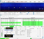
With the noise meter connected to IF output of the TVTR I pointed the dish to where I believed the minimum cold sky noise to be, adjusted the Zero Offset so that the noise meter read zero, and then went for “Gold” and set the K3NG rotator controller to auto-track the Sun.
As the rotator AZ and EL readings approached the heading for the Sun the noise meter needle shot up and back down. My first experience of just how “sharp” this new dish is, and it’s still only 1.2m! What would a 2.4m dish be like??? Now clearly the G-650C is sub-optimal here, a little too fast with a small element of backlash, albeit minimal, and just a simple 500R pot for positioning control but I still believed it could be a lot worse. After all, some of the problems and issues reported on various forums where the so called high-end AZ/EL rotators with HR positioning etc. are not able track accurately etc. do not inspire much confidence and if the question was asked probably most of the owners of these rotators still manually nudge the dish for optimum signal.
I knew that I would have to nudge the dish, and after a few goes with the AZ control buttons I was able to peak the noise level but the Sun noise was only around 6dB… I was so focused on the G-650 and AZ side of things I hadn’t even considered nudging the EL side! A couple of short taps on the rotator controller and the meter was reading 8.5dB of Sun noise. An absolute excellent result. Yes it was slightly down on what was calculated but I put that down to my ability to truly find the expected Cold Sky noise figure. Also nothing had been optimised on the feed side.
The short video below shows how the level of Sun noise changes with short nudges of the dish (the noise meter is set for 10dB full-scale). Note that the EL was not adjusted in the video to peak the noise reading.
The EL side of my setup uses a satellite actuator and this works extremely well. I found that the new dish alignment was different to the original 65cms dish hence the extra nudging required in the early tests. Once I had recalibrated things it tracked very well.
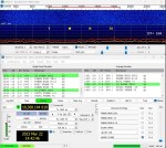
The next test was to see how well I could decode the DL0SHF EME beacon and if I could measure anywhere near the calculated 0.4dB of Moon noise. The rotator was able to “find the Moon” from its park position and track with decodes from the beacon for well over an hour. Were they the best decodes, no not always. The reports varied from -9dB to -14dB, but what was key here for me was the dish was “on the Moon”. With careful nudging I could decode for many periods at -8dB or -9dB which was comparable with others that were active with 1.2m dishes at that time. Oh, and Moon noise? I was able to measure just over 0.3dB so again an excellent result in my eyes.
Manual tracking and decoding of DL0SHF over a 26 minute period.
I repeated these tests over a few days just to ensure that the results were consistent and compared them with two other locals who also have a 1.2m dish setup. The results would seem to suggest that things are working pretty well on receive.
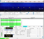
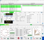
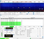
DL0SHF Beacon – G650C auto tracking over 30 minute period.
The above screen grab from Map65 shows the decodes from DL0SHF over a 30 minute period where the G-650C rotator is auto-tracking the Moon. You can see a 4dB variation over that period with -8dB being the best decode. With manual control, and peaking on Moon noise it’s possible to track and keep the beacon close to consistent -9dB as demonstrated in an earlier photo.
Over the last few weeks I have received and decoded 16 Initials (unique stations, including the beacon 🙂 ) via the Moon.


Lessons Learnt:
- It’s better to get on and use what you’ve got rather than having kit sat on the shelf waiting for that ultimate solution.
- With care and attention to detail a good small dish EME receiving setup can be put together and give good results.
- Do not underestimate the head load. The combined weight of the dish, mount, rotators, TVTR +PA and counter-balance weights can really add up.
- The noise meter is a great instrument to have especially if you need to track manually.
- Setting the rotator AZ + EL park headings (in PstRotator) so that the dish is pointing at QO-100 satellite is very useful. An SDR tuned to 265.5MHz on the output of my G4 10GHz TVTR will receive the narrow-band transponder very well. It also a check for correct dish alignment.
What’s next:
- Upgrade the feed support arms.
- Try optimising the feed horn position to get a better performance baseline for the full coax setup.
- Swap over to a WG16 feed setup and redo the optimisation.
- Experiment with different feed horns.
- Try PWM speed control on the G-650C motor.
- Complete the new TVTR + PA enclosure.
