
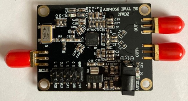
 Having used a number of these readily available “black ADF4351 boards” along with an Arduino Mini-Pro and SynthShield PCB in various projects I’ve learnt that not all the boards on sale are the same. They can differ both in component count and physical layout. The board size, positioning of the SMA and power connection are pretty much identical, so from a quick look at a sellers Ad you’d probably not notice the more subtle differences.
So far I’ve seen the following:
- The power connector pins can be in slightly different positions. This impacted the alignment of the power pins with the holes in the SynthShield PCB.
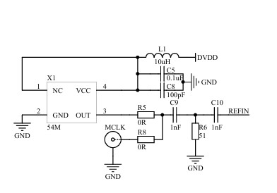
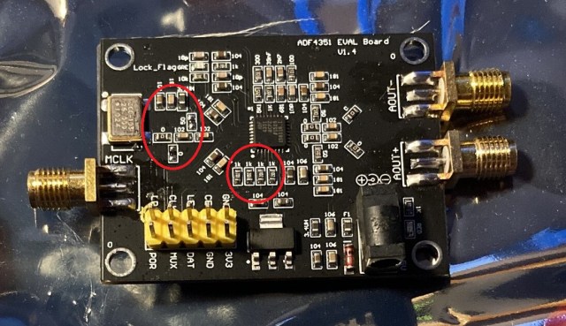
- To disable the onboard 25MHz source on most of the boards I’ve used I simply removed two SMD parts, the 0R link (R5) and L1 (Vdd feed). An external Frequency source (usually 10MHz) could then be used via the MCLK SMA socket. Two boards that I purchased recently were missing a 0R (R8) on the MCLK input track to enable the external source to reach the REFIN pin on the ADF4351 chip. So in addition to removing the two components a 0R needed to be soldered in place.
- A recent request for help from someone on the UKMicrowaves Group Forum highlighted that some boards appear now not to have a pull-up resistor on the CE pin. The two boards I mentioned previously also had this issue, a 10K resistor (R16) was missing. Having learnt this I revisited a board purchased last year that failed to work and had been relegated to my “useful scrap parts” drawer. This board was also missing the pull-up resistor, adding a 10K R between the CE pin and +3.3V resolved the issue and now it does indeed work!
The following photos show some of the board differences:
 The photos above and below show two boards that have had the standard power connectors removed in preparation for use with a SynthShield PCB and the different component layouts.
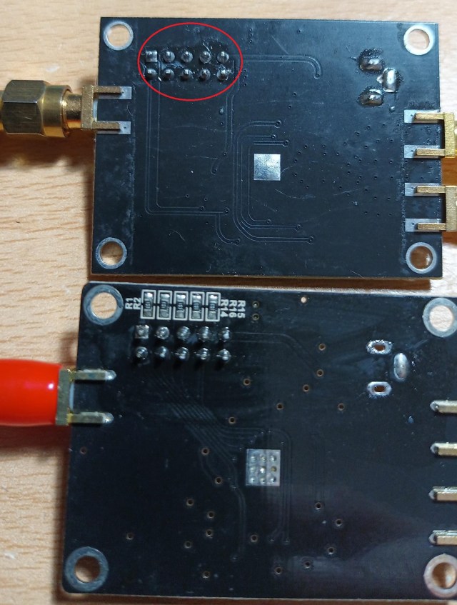
 This photos shows the 0R (R8) not present.
None of the differences described here are a major issue, if you are aware of them.
Hopefully these notes prove useful, and another board doesn’t get assigned to the “useful scrap parts” drawer as mine did last year. 🙂
Acknowledgements:
- Members of the UKMicrowaves Group for highlighting the missing CE pull-up resistor.
