

I spent a long time looking at the various power amplifiers being advertised for QO-100 use. My ideal unit being one that could be used for both QO-100 and normal 13cm terrestrial operation down at 2320MHz. It could be a kit, an off-the-shelf unit or a surplus unit requiring modification but one with a proven documented method to make it work.
I settled on an ex-UMTS power amplifier board that was being sold on eBay. It ticked all the boxes, the price was extremely attractive and most importantly for me it had a well documented modification process by SP8XXN and SP5MU.
The parts arrived very quickly and were exactly as described. I’d downloaded the modification instructions and quickly read a few other related posts on various forums. The hardest part I could foresee would be mounting the PCB to a suitable heat sink. The two LDMOS type BLF7G22L-130N devices and the circulator on the output sit below the bottom surface of the PCB so ideally three recesses need to be milled into the heat sink. Not having access to a milling machine I decided to use a thin sheet of copper with suitable cutouts to allow everything to sit flush on the heat sink.
 The photo above shows the thin copper sheet “gasket”. Great care was taken deburring all the holes and cut-outs.
The heatsink was marked up, drilled and tapped and the various parts of the power amplifier were assembled.
With a 50 Ohm load attached to both the input and output I applied a reduced voltage (22V) supply to the board. No magic smoke escaped but the board was immediately drawing over 4A! It appeared to be self-oscillating, I assumed that this was most likely due to earthing issues. I removed the PA board from the heat sink to check the surfaces and component levels with the straight edge of a ruler and discovered to my surprise that each of the power connectors had two very small plastic locating pegs that protruded beyond the bottom surface of the PCB. I had missed these four protrusions!
 The two red circles show where the four plastic locating pegs are.
I very carefully trimmed those back and made sure they would no longer cause a gap between the underside of the PCB and the copper sheet / heat sink. I was also concerned that the carefully hand lapped surface of the old second-hand heat sink would not provide good enough earthing so I decided to add a second sheet of copper to provide a better conductive surface.


The PA was reassembled and retested, this time the quiescent current (680mA) was much closer to that expected.
My goal was to achieve a maximum output power of around 20W – 25W but to run the amplifier at just 4W to 5W output when operating in the narrow-band segment of QO-100. The various online notes offered varying levels of change to improve the efficiency and power output at 2.4GHz. Some of the changes described were to alter certain tuning tabs, removal of the circulators and changing the bias circuit / class of operation. I wanted to make the minimum number of changes. I decided to initially just remove one capacitor on the input and modify the matching of each transistor as described here.
The input and output matching of each device was adjusted slightly by adding / removing copper foil and with these modifications, with the amplifier still operating in Doherty mode I was able to measure ~31W output into a 50R dummy-load for around 2W input.
Having got this far the next challenge was to work out how to switch the PA “off” on receive. Again reading online there seemed to be two approaches to biasing the PA.
- Where the PA was to be kept pretty much standard (Doherty) it seemed the common approach was to either switch off the 28V supply to the entire PA board or just to the bias circuit on receive.
- If the objective was to use the PA for DATV (where much more output power is needed) the common approach was not to use the onboard bias circuit and add a new switched bias supply board.
Thanks to the hard work by G8UGD and his posts on the Amsat-DL forum I was able to get a schematic of the onboard bias circuit. In fact most of what I experienced the hard way in my build was already well documented on the forum. I shared this schematic with a uW ELMER and asked for his advice on how best to switch the PA “off” on receive.
For my use, I was recommended to retain the original Doherty biasing as this offered additional functionality such as temperature tracking. It was suggested that I short the junction of the 13K5/1K (marked 3V75) to ground via a 1K resistor, this would cut-off both bias supplies and drop the bias voltages below cut-off.
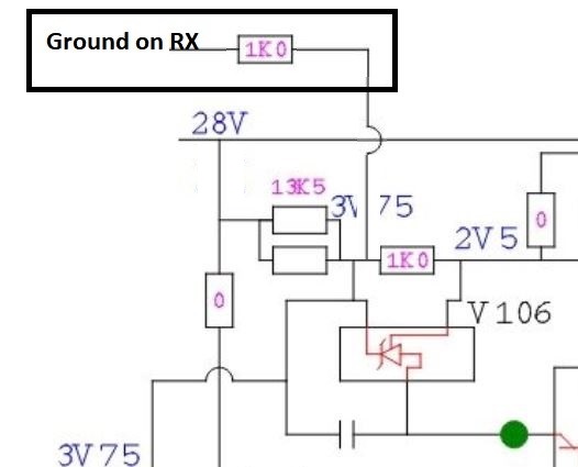
Section of Bias circuit showing where to add control line.
I added the 1K resistor as suggested, this is switched to ground on receive by a relay on my homebrew upconverter. I also 3D-printed some guides to help secure the 28V connections to the amplifier PCB. This completed my modifications, and the end result met with my requirements.

I am currently using the PA on the narrow-band section of QO-100. It runs with the DC supply set to ~24V and drive levels set for a maximum of 5W output. With the fairly long run of coax I have to the dish feed and a 95cm OS dish my signal is typically 6dB down on the beacon which I find to be ideal.
The end result is a PA that is not exactly small in size or especially efficient but it serves my needs. It was not expensive and provided a good learning curve, plus it can still have additional modifications made to improve the maximum output power and efficiency if ever needed.
