
 Most of my 10GHz activity to-date has been on EME, followed by RS (Rain Scatter), i.e. the reflection of signals off rain cells. I do not live on the top of a hill with a clear take-off so RS offers the possibility to make contacts over obstructed paths. Most of my RS activity has been done using a small indoor dish setup pointing skywards out through the patio doors. To work via distant rain cells rather than reflecting on what’s more or less above my location I would need to get a system up above roof height, with ideally some elevation control, and have around 2W of RF output.
I needed another transverter!
If I was going to go to the effort of building another one it would need to work seamlessly with my existing shack based back-end equipment that’s used for EME i.e.:
- It would use a 144MHz IF to work with my K3 and Anglian transverter. This would then also allow me to use SDR-Console to view the band, plus all the various digi-mode software already setup for the K3.
- Be GPSDO locked for accurate frequency and stability control.
My recently finished transverter for portable operation started out with the intention of using a 144MHz IF but I found that the unwanted mixer products could not be suppressed sufficiently using just the onboard pipe-cap filters on the LO and TX modules. So I took the easy route and simply changed things to work with a 432MHz IF. To use 144MHz much better filtering would be needed. later an online search resulted in an excellent QEX article by Paul – W1GHZ describing the construction of post-filters that use a section of waveguide. With this information I decided to build another modular setup based largely around the modules I had used previously. This build would however use two modules that had been sat on the shelf for many years. One was a G4DDK-004 LO module and then other a G3WDG-002 RX module that I started back around 1996.
I have modified the G4DDK-004 LO module to injection lock the crystal oscillator with 106.5MHz from a Leo Bodnar GPSDO and added a Kuhne LNA on the receive side. On the transmit side the output from the W1GHZ based TX module was amplified by a “Franco” driver stage and finally a PMA5-123 PA. More information on these modules can be found here.
The post-filter proved to be fairly easy to construct using basic metalwork tools and a gas blow lamp to solder the parts in place. At the time I built the filter my 10GHz test facilities were fairly limited and so the filter was basically tuned for maximum throughput at 10368.200MHz. Here are a few photos giving an idea of the construction.
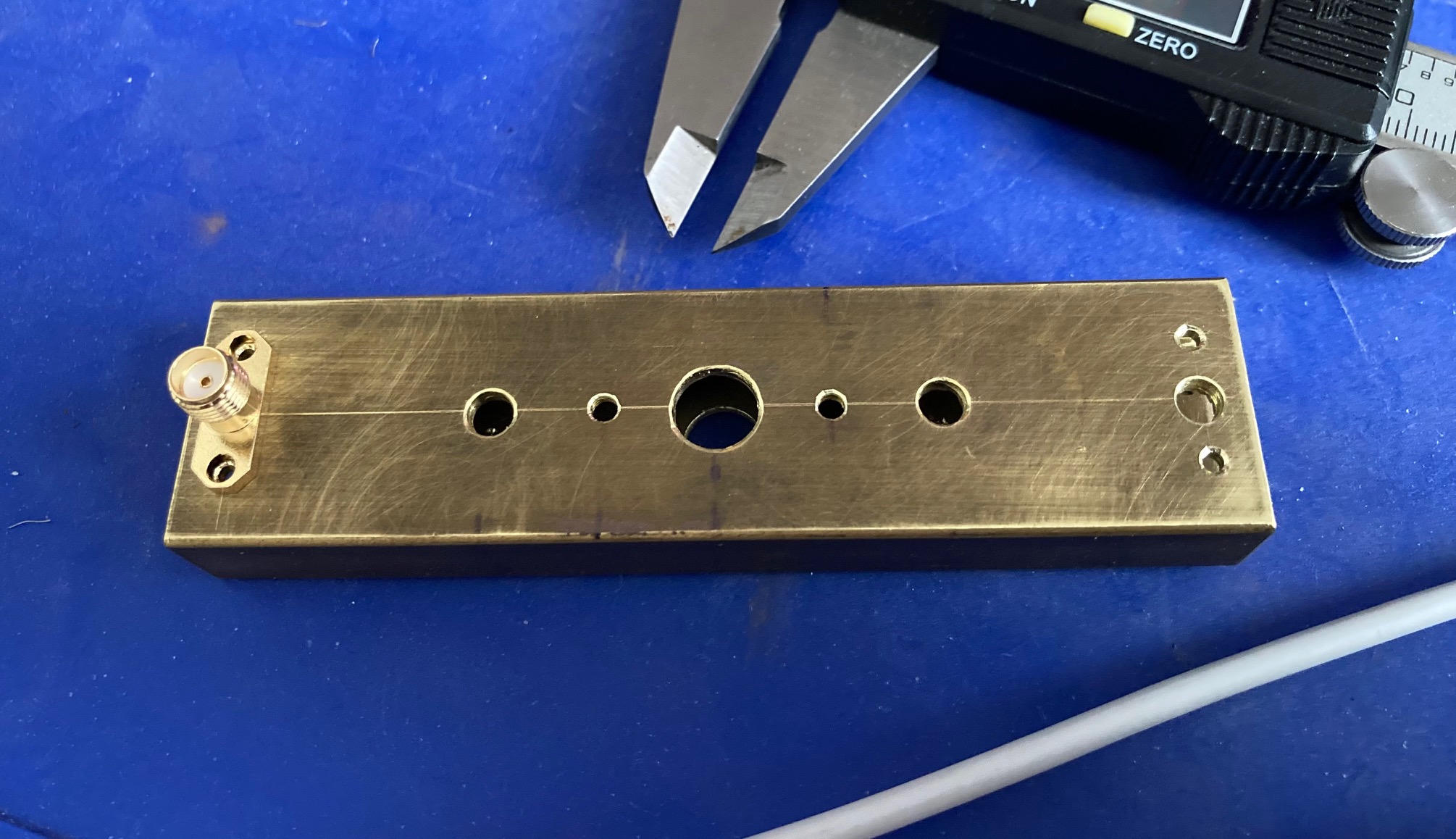


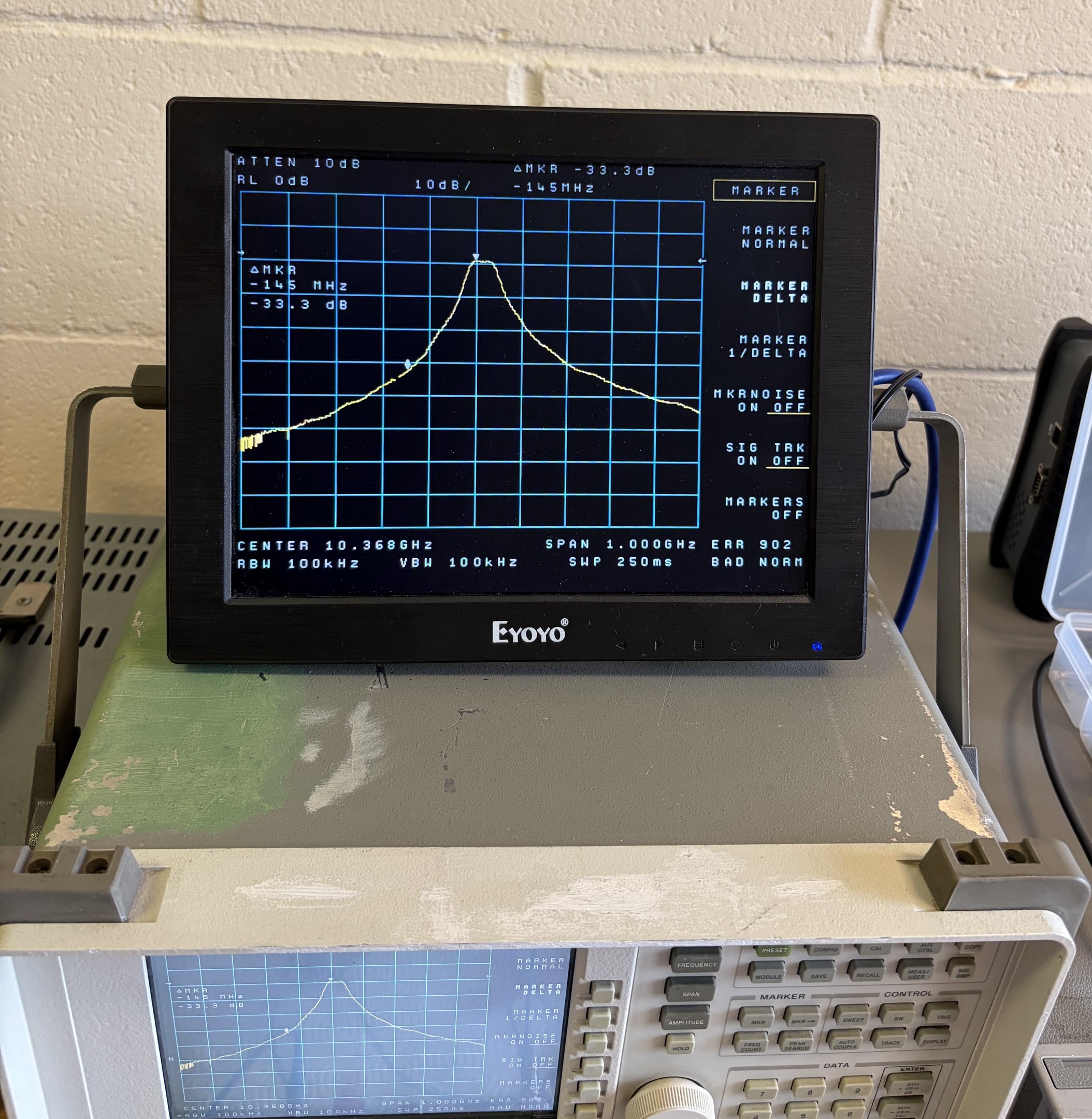
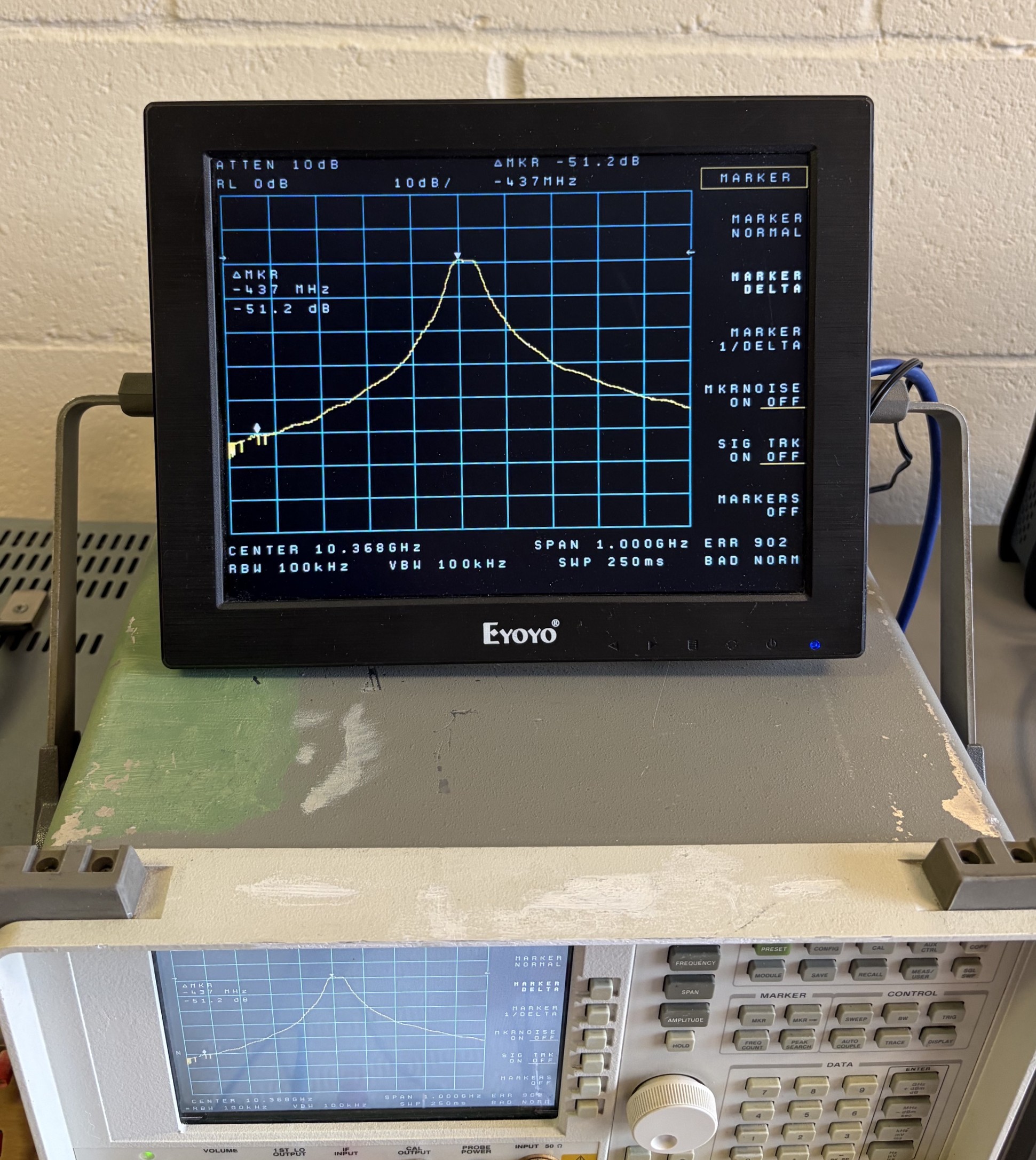
The filter characteristics were kindly measured by Roger – G8CUB at the Ridgeway Microwave Round-table. The results exceeded my expectations. The filter provided 33dB rejection at a frequency 144MHz away from the operating frequency (LO Leakage) and 51dB rejection 432Mhz away with an Insertion Loss (IL) of 1dB.
With the addition of the new filter the output looks quite respectable. With the desired 144MHz IF all unwanted spurs appear to be better than -55dBc
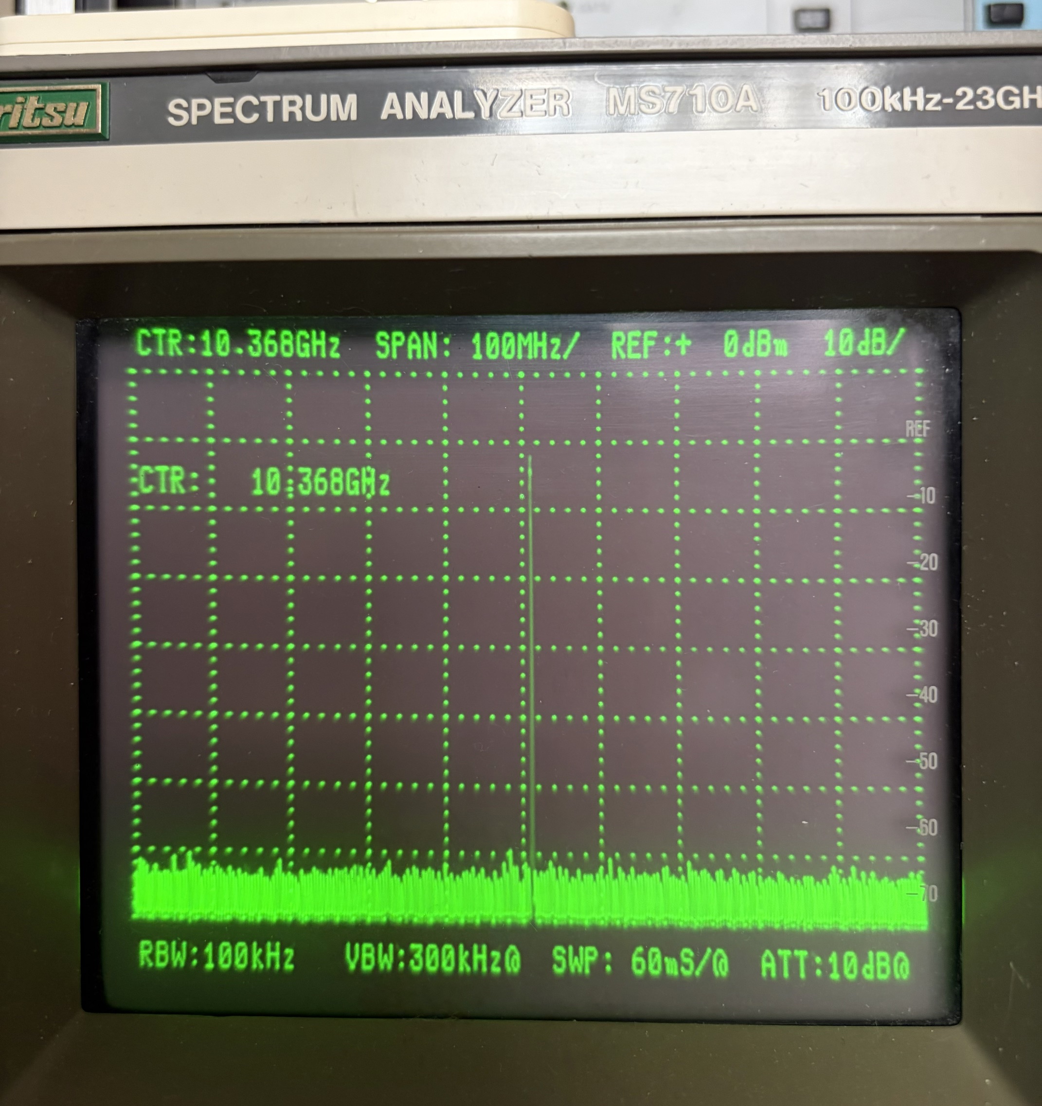 The rather poor screen-grab above shows +/- 500MHz either side of the wanted signal (the trace is showing high in frequency as the SA had only just been turned on).
A Hammond die-cast box is used to house the transverter, from the outset I knew things were going to be a tight fit. It really was a challenge to shoe-horn everything in. Here are a couple of photos showing the basic build. The underside of the internal Ali sheet chassis has the LO, PSU, sequencer and RX modules and the top side has the TX modules and filter.

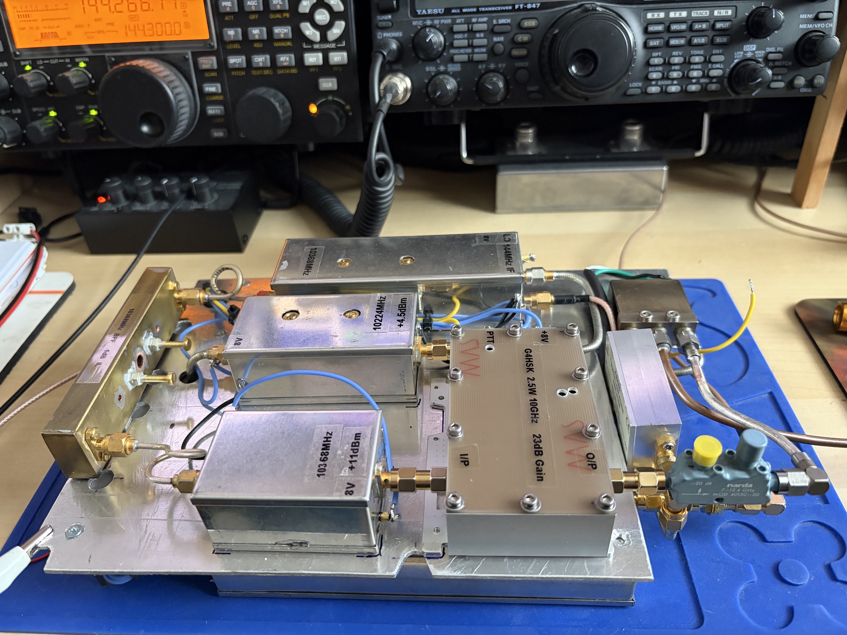
The photo above shows a Narda directional coupler on the output of the 2.5W PA. This was being used for power and SA measurements during testing. It’s has been replaced with an isolator in the finished build.
With the exception of the Kuhne LNA and two DC-DC buck converters all the modules are homebuilt and cover over 30 years or microwave technology. The G4DDK and G3WDG modules from around 1996 to the PMA5-3W MMIC SSPA built in 2026.
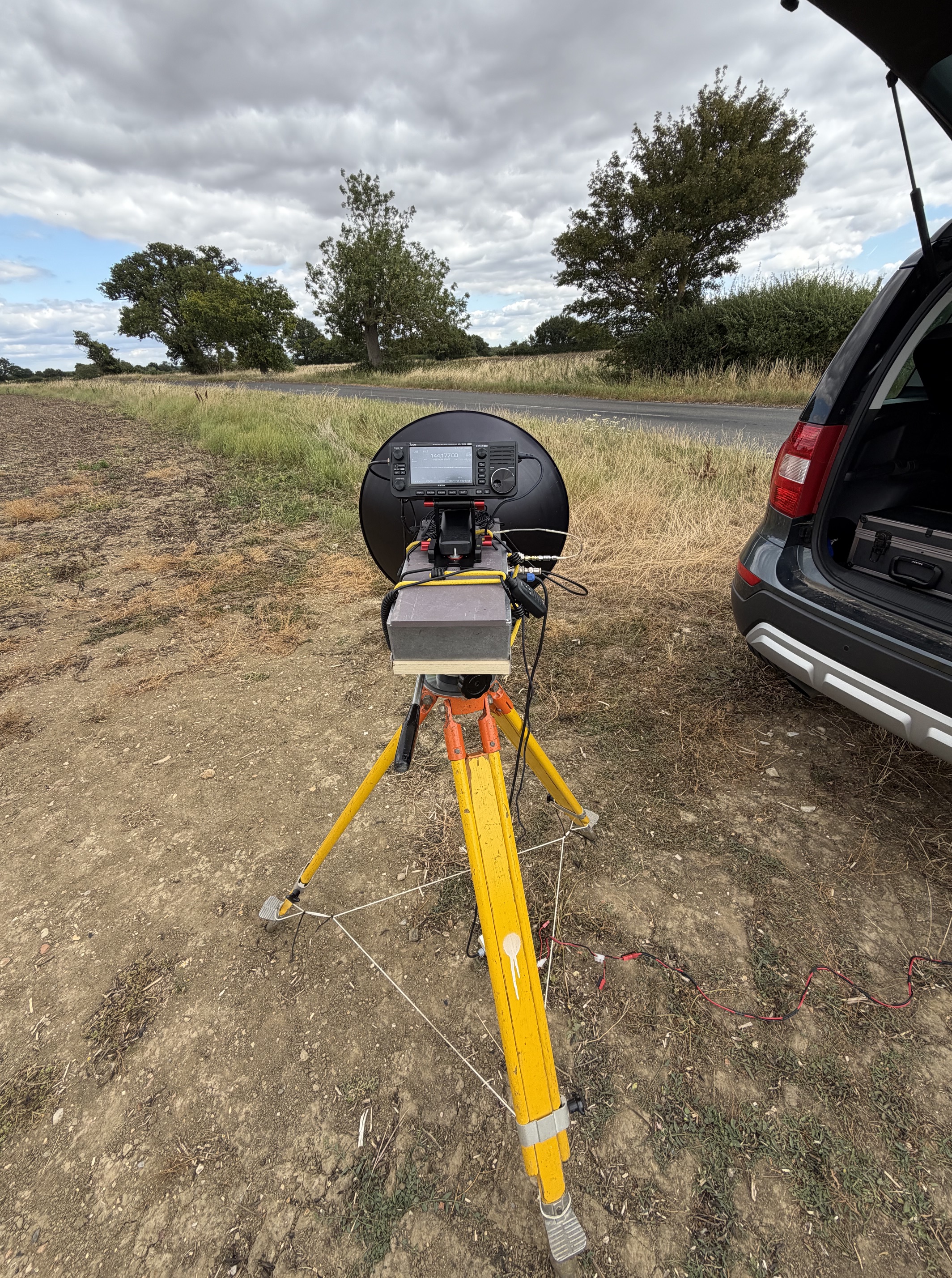
I’ve used the finished transverter a couple of times out portable. Here’s a photo of it mounted on a surveyors tripod. A Leo Bodnar LBE-1420 GPSDO providing the LO injection locking, an IC-705 for the 144MHz IF. 2W to a PW dish with Penny-feed.
Lessons Learnt
- I found that on odd occasions certain combinations of waveguide feeds / dish setups could cause the PA protection circuit to trip. Adding an isolator on the output of the PA resolved this.
- The Leo Bodnar LBE-1420 GPSDO needs to be set to Low Power Output and have a 6dB attenuator inline to provide the correct injection level (106.5 MHz) to lock the G4DDK-004 LO.
Next Steps
- Fit a breathable vent in the die-cast box and gasket.
- Construct the brackets to fix the transverter and dish to the mast and allow for +/- 15 degrees Elevation.
- Run some PN (Phase Noise) measurements of the 10GHz output when using the Leo Bodnar GPSDO for injection locking vs a SynthShield ADF4351 PLL plus 10MHz OCXO.
- Get started on another uW band.

