
Having got to the point where my PA was working well I was keen to move forward with getting it into a suitable enclosure. A club member offered to 3D-print the two enclosures for me so that I could validate my design / dimensions etc before paying to have metal cut.
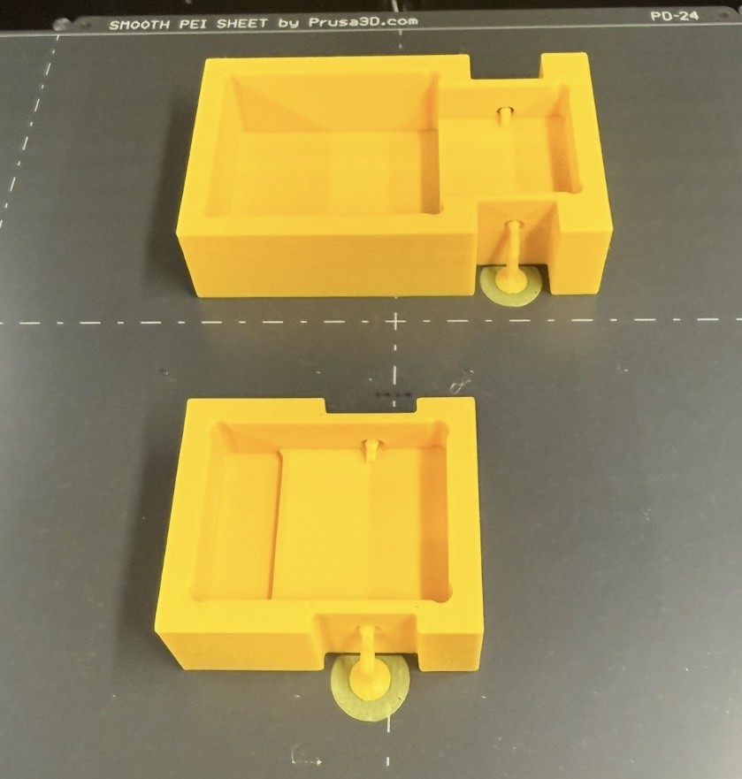
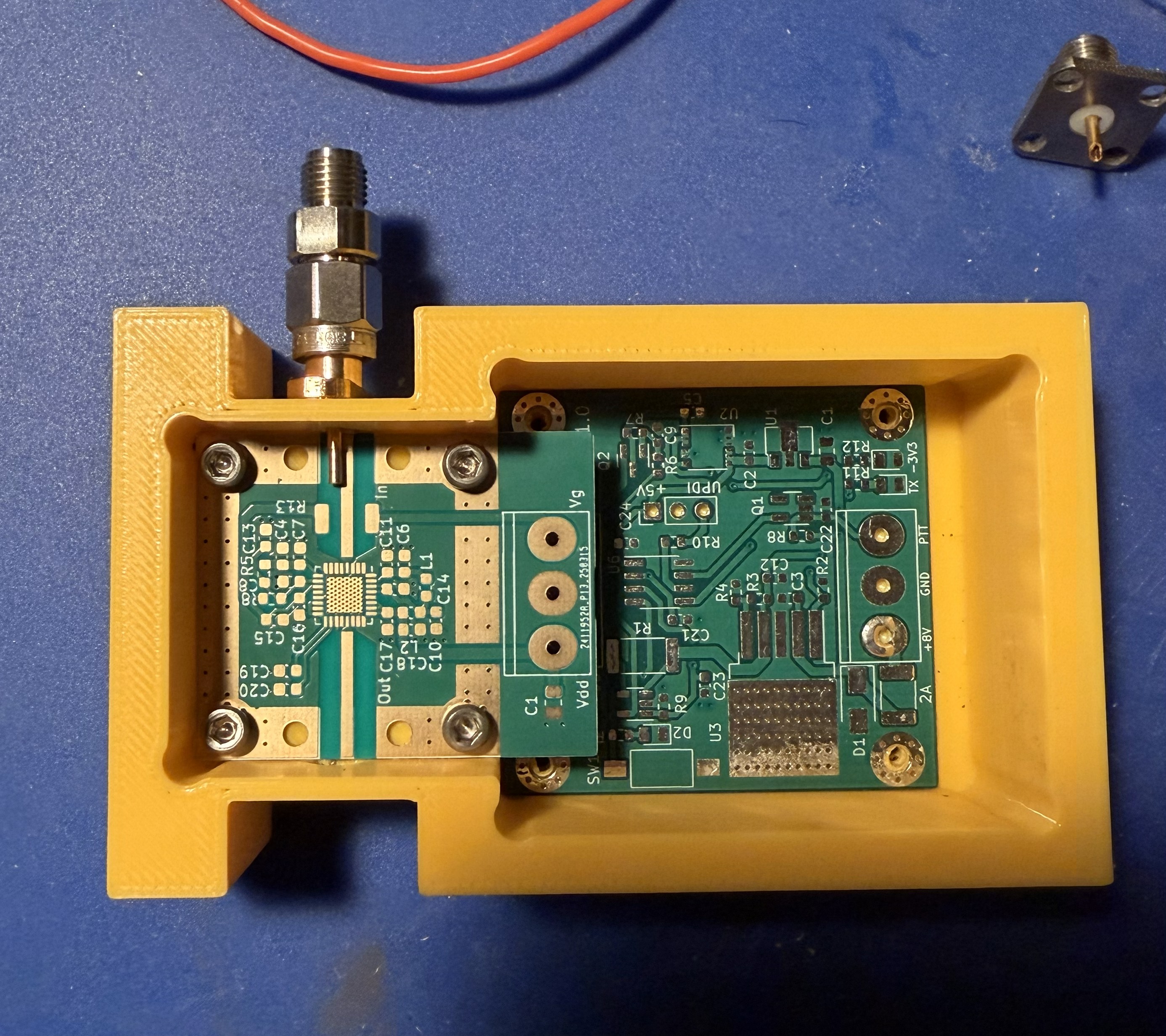
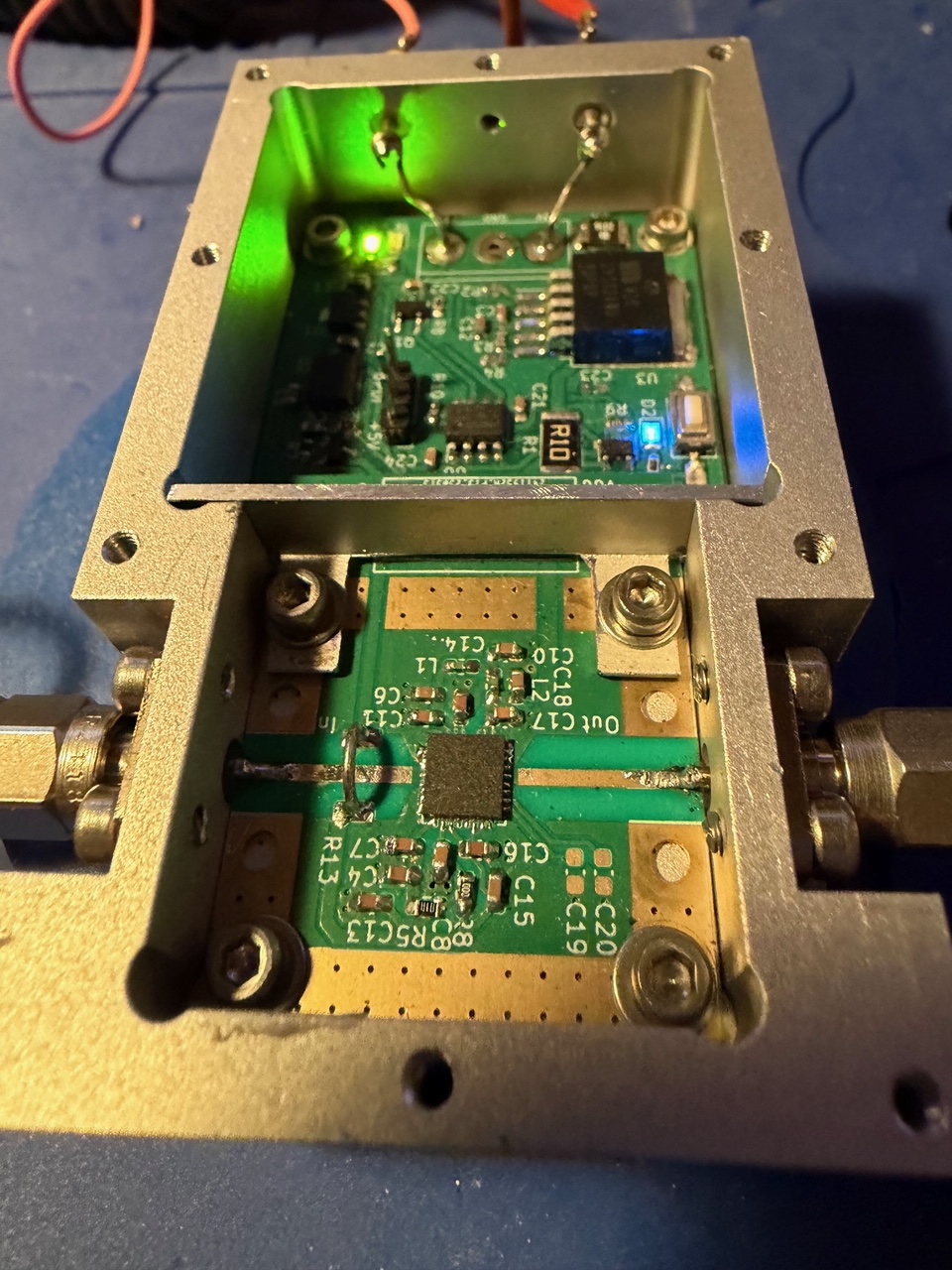
This proved to be a very worth while exercise as somehow I had managed to position the holes for the SMA connectors incorrectly! They did not align with the RF tracks as can be seen in the following photo:
 I soon fixed that and a step file was uploaded to JLCCNC. They were offering a discount on shipping at the time which I took advantage of and one week later I was examining my first CNC machined part.
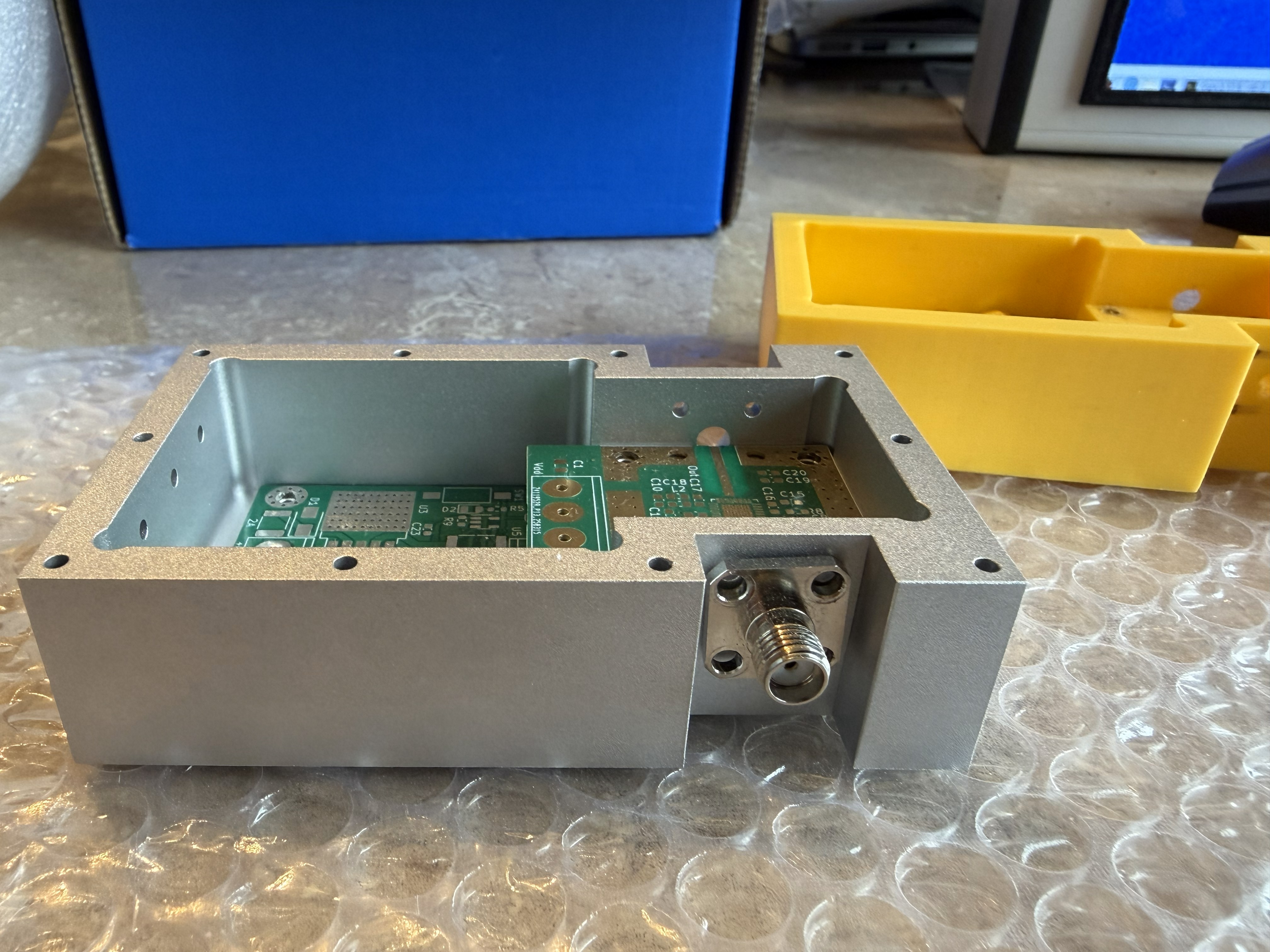
I opted not to have any of the holes tapped, this helped keep machining costs down, but it meant that I had 26 holes to tap! Fortunately all went well and I soon had the boards fitted in the prototype enclosure and everyting ready to run some tests.
The tests did not go well! I had the input and output configured just as before, but the PA had become an oscillator, even without a lid. Using a small sheet of aluminium as a lid with a piece of absorber material on the underside made little difference. Several hours were spent trying to tame the beast. I got it to a point where with a 2dB SMA attenuator directly on the input to the PA it appeared to be conditionally stable.
It was then suggested that I try adding a screen between the two sections to see if it helped. Fortunately the position of the PA board meant that it was a fairly easy thing to do and it could be held in place by two of the fasteners. I made the screen from a small piece of 1mm thick Ali angle.
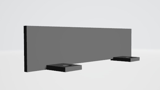
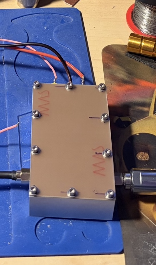
The photo below shows the screen fixed in place:
 This changed things completely, with the screen in place and the piece of absorber on the underside of the lid the amplifier no longer oscillated.
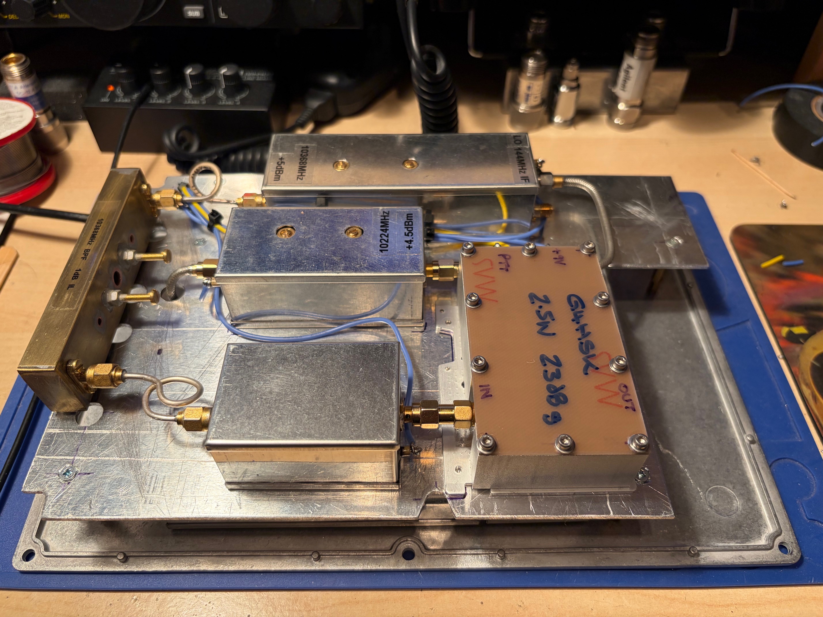
Here’s the PA with its lid fitted, going through a series of tests with different lengths of semi-rigid connecting cables, SMA to WG transitions and feed horns.
For now the lid is simply made from an old offcut of PCB material. Aside from a fancy Ali lid it’s basically complete, working and going to be used as final stage of a homebrew transverter.
Here’s the new modular transverter with the PA, a mix of old school with new GaAs MMIC PA that’s currently measuring 2.5W output, 23dB gain:
Acknowledgements:
- Thanks again to Kent – WA5VJB, Maarten – PA0MHE and Rens -PA3AXA (and possibly others I’m not aware of) for their part in this project. All the information needed, i.e. BOMs, Gerbers, ATtiny SW etc can be found here.
