
 My goal is to have around 1 to 2W of output power from the 10GHz /P transverter. This power level would be ideal for working Rain Scatter (RS). The basic upconverter produces around 5mW. I’ve yet to find a power amplifier (PA) to do the job at a reasonable price and certainly not one requiring just 5mW input. So the first step needed to be to increase the output to around 100mW.
Fortunately I had a couple of the “Franco” SU-02 10GHz Boards that were part of a recent group buy organised by Phil, G3TCU. These boards appear to have been available for a number of years and as a result there have been many excellent articles describing how to make good use from them.
What I’m showing here is the practical approach and end result of a project based primarily on an article by Geoff, GI0GDP published in an issue of Scatterpoint Newsletter that’s available to all UKuG members.
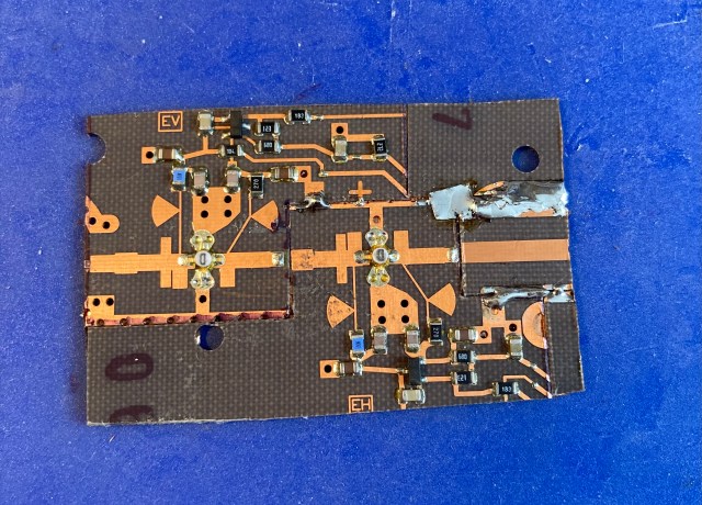
The SU-02 board looks like this:

It has four devices that can be put to good use. Lots of useful information can be found here
The following series of photos show how the final driver amp patchwork is made up from various sections of the original SU-02 board.
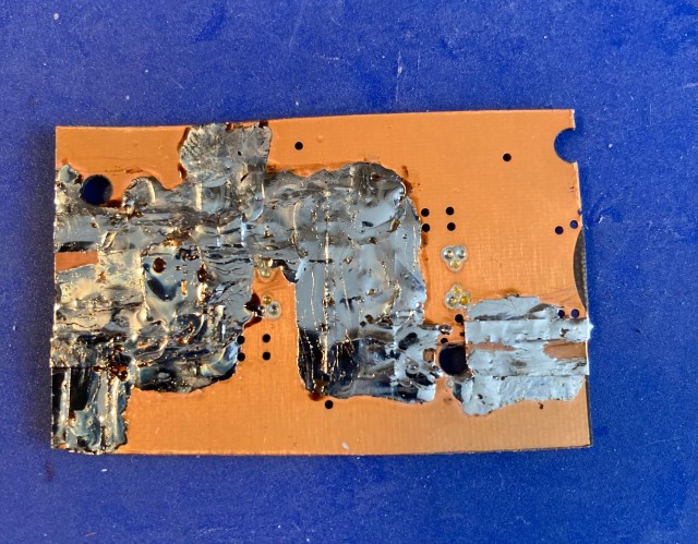
 Adhesive copper tape was used on the underside of the board to “knit” all the sections together. It was also tinned to ensure a good ground plane.
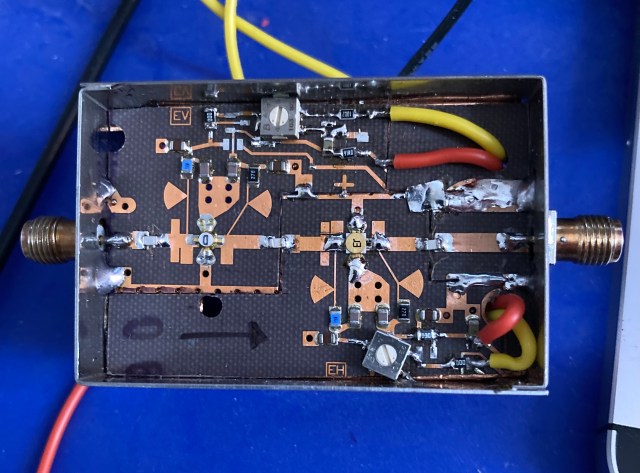
 Once I had formed the new two-stage board it was trimmed to size to fit in one of the standard “German Tin Boxes”. The red lines in the photo below indicate the shape of each of the patchwork sections.

The various components that were part of the active bias circuit were also removed and two trim-pots added for the new bias arrangement.
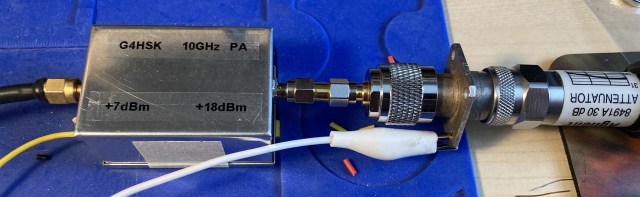
Just to prove that my patchwork would still produce some RF output and not let out any “Magic Smoke” I ran some tests with the two original NE32854 devices and the modified bias arrangement. This setup used the PSU section from the “Franco” board.
The following photo shows the original PSU section.
 With this configuration I was seeing around 25mW output, things being limited by compression, but it was still amplifying and no smoke!
The next stage was to replace the second device with a MGF1601 and change the bias / PSU arrangement.
With some copper foil carefully positioned to act as a heat shield the NE32854 ws removed using a hot air gun.
 Here it is with the pads suitably cleaned up:
 The MGF1601 was soldered in place and a new PSU cobbled together using a section of PCB from another project.
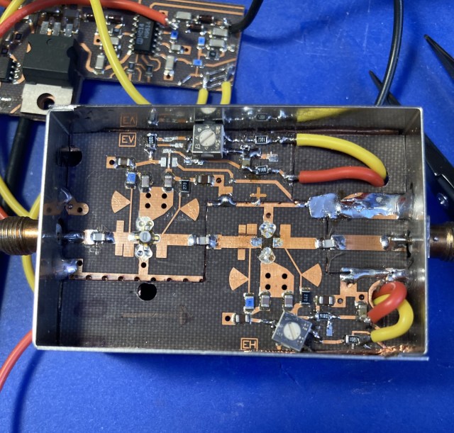
With the new driver amp module installed in my transverter I’m currently measuring 75mW output.
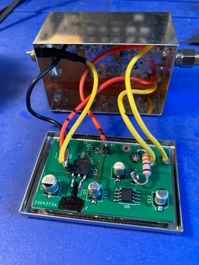
The photo below shows the new module installed in the TVTR enclosure.

The top cover of the tin box did cause some instability. Fortunately this was easily resolved by glueing two retangular pieces of RAM to the underside of the cover.
Taking into account the additional loss of the second WG16 to SMA transition (for the power meter) plus various SMA connectors / adapters I suspect that the transverter is putting just under the desired 100mW into the horn / dish feed.
Acknowledgements:
- Geoff, GI0GDP for his article published in the UKuG Scatterpoint Newsletter.
- UKuG and others for the detailed information on the “Franco” SU-2 10GHz PCB
- Phil, G3TCU for undertaking the recent group buy of the SU-2 boards.
